
Plane Beam Approximations: Visualization Tools
Difference Between Euler Bernoulli and Timoshenko Beams
The following tool analyzes a cantilever beam of length 10 units and height of 1 unit under an upward unit load. The displaced shape of the beam is drawn for various values of  and
and  The Euler Bernoulli beam has a deflection less than the Timoshenko beam for a small value of
  . Notice that plane sections remain plane for both beams. For the Euler Bernoulli beam, the sections perpendicular to the neutral axis remain perpendicular after deformation, while this is not the case for the Timoshenko beam. At higher values of
  (higher shear stiffness) the displacement of both beams are almost the same. Can you comment on what ratio of
  that would warrant the use of the Timoshenko beam approximation for this cantilever beam?
Euler Bernoulli Cantilever Beam
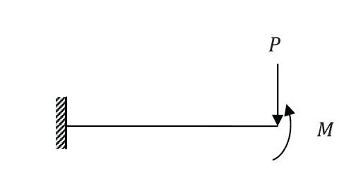
The deflection of the centerline of a cantilever Euler Bernoulli beam loaded at the right end with a shearing force  and a bending moment M (See figure below) follows the following equation:
![\[y=\frac{3MX_1^2-3LPX_1^2+PX_1^3}{6EI}\]](https://engcourses-uofa.ca/wp-content/ql-cache/quicklatex.com-59aad6259a17310d765bded7692b6e38_l3.png "Rendered by QuickLaTeX.com")
which can be obtained using the following Mathematica code:
View Mathematica Code
Clear[a,x,V,M,y,L,EI]
M=EI*D[y[x],{x,2}];
V=EI*D[y[x],{x,3}];
th=D[y[x],x];
q=0;
M1=M/.x->0;
M2=M/.x->L;
V1=V/.x->0;
V2=V/.x->L;
y1=y[x]/.x->0;
y2=y[x]/.x->L;
th1=th/.x->0;
th2=th/.x->L;
s=DSolve[{EI*y''''[x]==0,M2==Mom,V2==PP,y1==0,th1==0},y,x]
View Python Code
from sympy import *
import sympy as sp
sp.init_printing(use_latex = "mathjax")
x , EI, a, L, Mo, P = symbols("x EI a L M P")
y = Function("y")
th = y(x).diff(x)
M = EI * y(x).diff(x,2)
V = EI * y(x).diff(x,3)
q = -a
M1 = M.subs(x,0)
M2 = M.subs(x,L)
V1 = V.subs(x,0)
V2 = V.subs(x,L)
y1 = y(x).subs(x,0)
y2 = y(x).subs(x,L)
th1 = th.subs(x,0)
th2 = th.subs(x,L)
s = dsolve(EI*y(x).diff(x,4), y(x), ics = {M2/EI:Mo/EI, V2/EI:P/EI, y1:0, th1:0})
display(simplify(s))
The deflected shape can be visualized for  units and
  units with a beam height of 1 unit using the following tool with
  and
and 
Timoshenko Cantileaver Beam
The deflection  and cross section rotation
  of the centerline of a cantilever Timoshenko beam loaded at the right end with a shearing force and a bending moment
  (similar to the Euler Bernoulli beam above) follows the following equations:
![\[y=\frac{-6EIPX_1+3kAGMX_1^2-3kAGLPX_1^2+kAGPX_1^3}{6EIkAG}\qquad \psi=\frac{2MX_1-2LPX_1+PX_1^2}{2EI}\]](https://engcourses-uofa.ca/wp-content/ql-cache/quicklatex.com-0528213094eeb9517fd7d00445f56eb4_l3.png "Rendered by QuickLaTeX.com")
which can be obtained using the following Mathematica code:
View Mathematica Code
Clear[a,x,V,M,y,L,psi,EI,kAG]
M=EI*D[psi[x],x];
V=EI*D[psi[x],{x,2}];
q=-a;
M1=M/.x->0;
M2=M/.x->L;
V1=V/.x->0;
V2=V/.x->L;
y1=y[x]/.x->0;
y2=y[x]/.x->L;
psi1=psi[x]/.x->0;
psi2=psi[x]/.x->L;
s=DSolve[{EI*psi'''[x]==q,psi[x]==y'[x]+EI/kAG*psi''[x],y1==0,psi1==0,M2==Mom,V2==P},{y,psi},x]
View Python Code
from sympy import *
import sympy as sp
sp.init_printing(use_latex = "mathjax")
a, L, x , EI, psi, kAG, C1, C2, C3, C4, Mo, P = symbols("a L x EI psi kAG C_1 C_2 C_3 C_4 M P")
q = 0
#This seems like the output is incorrect???
EIpsi = integrate(q,x,x,x) + C1*x**2/2 + C2*x + C3
EIy = integrate(q,x,x,x,x) + C1*x**3/6 + C2*x**2/2 + C3*x + C4 - EI/kAG*(integrate(q,x,x) + C1*x)
M = EIpsi.diff(x)
V = EIpsi.diff(x,2)
M2 = M.subs(x,L) - Mo
y1 = (EIy/EI).subs(x,0)
psi1 = (EIpsi/EI).subs(x,0)
V2 = V.subs(x,L) - P
s = solve([psi1,y1,M2,V2], [C1, C2, C3, C4])
display(s)
EIpsi = EIpsi.subs({C1:s[C1], C2:s[C2], C3:s[C3], C4:s[C4]})
EIy = EIy.subs({C1:s[C1], C2:s[C2], C3:s[C3], C4:s[C4]})
display("y = ", simplify(EIy/EI))
display("psi = ", simplify(EIpsi/EI))
The deflected shape can be visualized for units,  units, and units with a beam height of 1 unit using the following tool with
  and
and 