
Plasticity: Physical Behaviour of Metals
Experimental Observations in a Uniaxial Stress State
When a metal specimen is loaded in a uniaxial state of stress along the direction of the basis vector  , the relationship between the engineering stress
  measured as the force divided by the original area and the engineering longitudinal strain
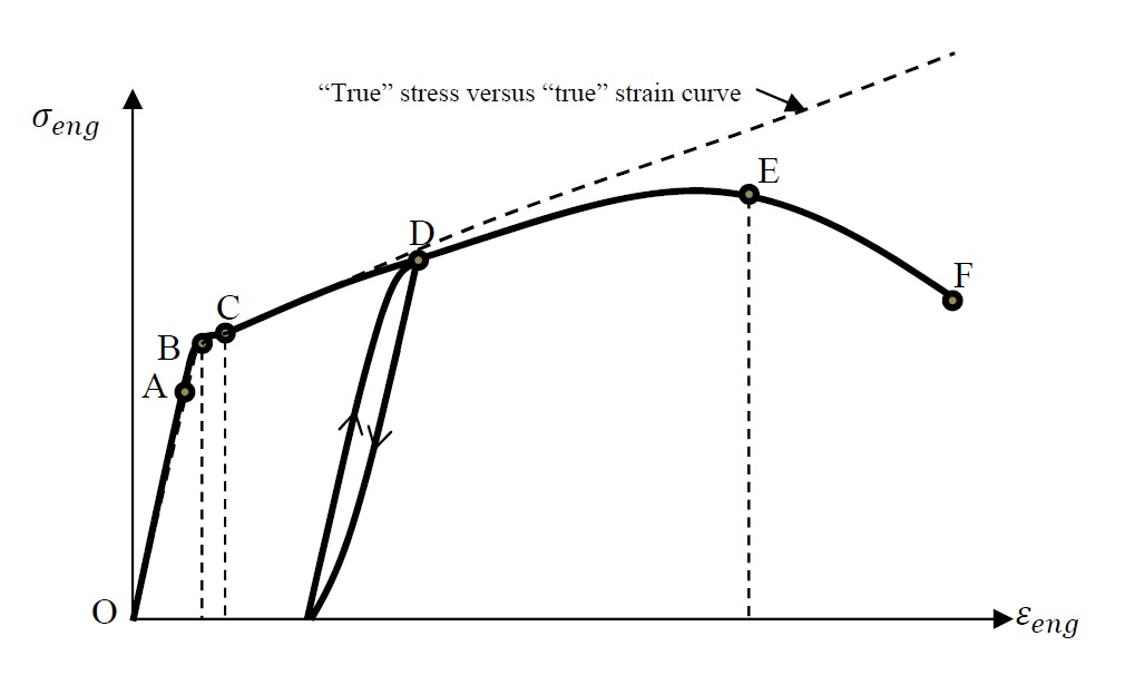
  along the direction of the vector follows the typical curve shown in the Figure 1 below.
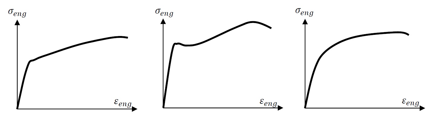
The behaviour is usually divided into four different distinct regions. The first region is the elastic region which is described by the curve OAB. In this area, loading and unloading follows the curve OAB and thus, there is a unique relationship between the stress and the strain. The point A describes the limit of linear proportionality between the stress and the strain. Following that point on the curve, there could be a slightly nonlinear portion exhibited in the curve AB and the extent of the nonlinearity usually depends on the metal alloy. In some high strength steels, the nonlinearity in the region AB is more evident than regular mild steel. The second region, presented by the portion of the curve BC, is the yielding region where the metal seems to hit a stress value after which the strain increases without an increase in the stress. Once the stress reaches any value higher than the value at point B, and upon unloading, the metal exhibits permanent deformation. Mild steel usually exhibits a very apparent yielding region where the stresses corresponding to point C could even be lower than that corresponding to point B. The third region, termed the strain or work hardening region, is the region between points C and E. In this region, the strain increases with the applied stress but with a slope that is much lower than that of the elastic region. In this region, if the stress is removed and later reapplied, the metal behaves almost elastically with the same slope of the linear region, but with a yield stress (the stress corresponding to point D) that is higher than the initial yield stress (stress corresponding to point B). When the applied load is removed, the metal specimen exhibits a permanent strain that is termed: “plastic strain”. Upon reapplication of the stress, the metal behaves elastically until it reaches a yield stress that corresponds to the point D. The yield stress is thus history dependent as it depends on the amount of plastic deformation or plastic energy that has been utilized to deform the metal previously. The term “strain hardening” might seem counter intuitive since the stress strain curve seems to have a slope that is decreasing rather than increasing, but the “hardening” refers to the increase in the yield stress presented by the point D as the strain increases. In the fourth region, starting from point E onwards, the specimen usually necks and the area decreases rapidly until rupture at point F. The stress at point E is termed the ultimate stress while that at point F is termed the failure stress. In most applications, the two values are not distinct from each other. Different metal alloys can exhibit similar forms of the typical stress strain behaviours as shown in Figure 2 below.
The constitutive relationship between the stress and the strain is usually given in terms of the “true” stress and the “true” or logarithmic strain and is represented by the dotted line in Figure 1. The “true” stress is denoted by the component  of the Cauchy stress tensor
  while the “true” longitudinal strain in the direction of the basis vector is the natural logarithm of the component
  of the strain tensor
  .
.
Stress Reversals and the Bauschinger Effect
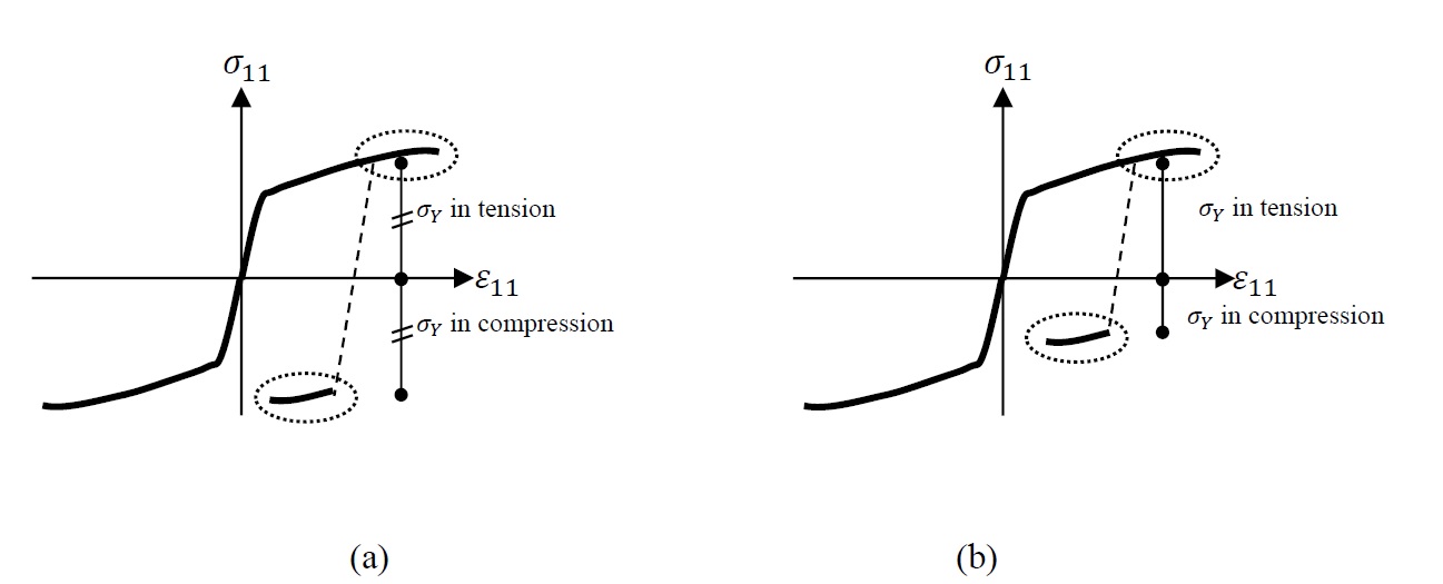
In some specimens, it is observed that the behaviour of metal specimens in tension and compression is similar and in fact, the yield stress in tension or in compression is the same (Figure 3a). However, in some other metals, the initial yield stress in tension is the same as that in compression but as the material is deformed in tension, the yield stress in tension is increased while that in compression is decreased (Figure 3b).
Metals exhibiting no Bauchinger effect exhibit, in most cases, an isotropic plastic behaviour. Bauchinger effect on the other hand can cause some apparent anistropic plastic behaviour. If a material is initially loaded beyond the initial yield in a certain direction, subsequent loading in that specific direction would be accompanied by a higher yield stress value compared to subsequent loading in other directions.
Other Physical Observations
Experiments have shown that yielding or plasticification of metals is due to the sliding of dislocations in the crystal lattice of the material along paths of minimum energy requirement. The movement of these dislocations is accompanied by no change in volume and thus, plastic or permanent deformations in metals are isochoric. In addition, the hydrostatic stress is found to have no effect on the yield stress of the metal. Metals that exhibit an initially anisotropic behaviour are not covered in these notes.
This open-source textbook is very helpful. Thank you for having it for everyone. I am currently studying and doing research in crystal plasticity, and I learned a lot from your website.
Thank you.