Plane Beam Approximations: Accuracy of the Beam Approximation
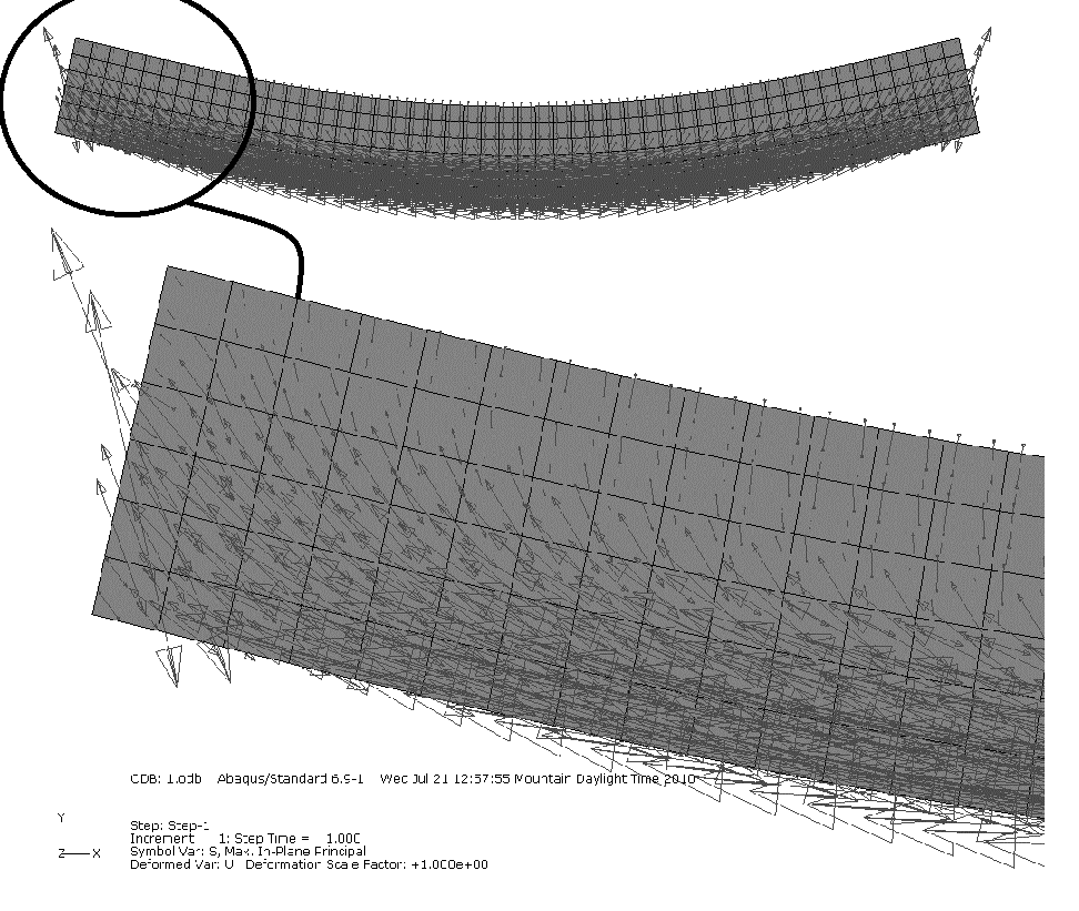
The beam approximation is used to analyze and design beams and frames under the effect of combined lateral loads, axial loads, and bending moments. In a coordinate system that includes the beam longitudinal axis, lateral loads lead to the development of “shear” stresses in the beam, and thus, the design codes include formulas for the design of beams under the effect of “bending” and “shear” stresses. When more detailed analysis of the stresses state inside a beam is required, finite element analysis of a beam could be more beneficial since it does not include the “plane sections remain plane” assumption and is able to more accurately characterize the stress state inside the beam. Figure 9 shows the arrows pointing in the direction of the maximum principal stresses obtained from a finite element analysis of a simple beam under lateral loading. The direction of the principal stresses shows that in the middle of the beam span, the maximum principal stresses are primarily horizontal and located at the bottom fibers of the beam. These stresses develop due to the higher bending loads at mid-span of beams under lateral loading. The direction of the principal stresses closer to the support, however, are influenced by the “shear” components of the support reactions and thus tend to be oriented at an angle that is dependent on the interaction between the bending and the shear loads. In concrete beams, for instance, cracks develop in locations closer to the support that are oriented perpendicular to the directions of the maximum principal stresses (direction of the maximum tension), and thus, “shear” reinforcement are required closer to the supports. Figure 9 shows that the orientation of the stresses obtained from finite element analysis, which is a better approximation than the beam approximation, are similar to those expected from the beam approximation. The accuracy of the beam approximation is normally guaranteed provided the displacements are small, and the beam cross sectional dimensions are much smaller than the longitudinal direction.M
This section presented the derivations for the classical small deformation plane beam theories. The extension to three-dimensional deformations is straightforward. For large deformations, the equations presented here are no longer valid. When the deformations are large, the use of the small strains tensor could be erroneous (see the section on small strain). In addition, when the equilibrium equations were derived in this chapter, the horizontal forces and the moment equation were uncoupled. However, for large deformations, the horizontal forces can have large effects on the bending moment induced in a beam. The Euler Bernoulli beam and the Timoshenko beam, as described in this chapter, do not include the effect of axial forces on the bending moment and thus cannot predict the phenomenon of buckling. In addition, no reference was given to any of the traditional or modern methods (the stiffness method in particular)for solution of frame structures composed of different beams connected together.