
Single Degree of Freedom Systems: Equivalent Mass and Equivalent Stiffness
We have seen that the form of the equation of motion for a simple spring{mass system is
![\[m\ddot{x} + kx = 0\]](https://engcourses-uofa.ca/wp-content/ql-cache/quicklatex.com-2b5c9a32f831eadeb954ae6e81eeeae1_l3.png "Rendered by QuickLaTeX.com")
Similarly, for a simple pendulum (undergoing small motions), the equation of motion can be written as
![\[m l^2 \ddot{\theta} + mgl \theta = 0\]](https://engcourses-uofa.ca/wp-content/ql-cache/quicklatex.com-313b5aedac05e10d232e2c6af3dff8dd_l3.png "Rendered by QuickLaTeX.com")
which has a very similar form. In general, for any linear undamped single degree of freedom system the equation of motion can be expressed in the form
![\[m_{EFF} \,\, \ddot{q} + k_{EFF} \,\,q = 0\]](https://engcourses-uofa.ca/wp-content/ql-cache/quicklatex.com-f653168bc8162fba1057389ba63a92ee_l3.png "Rendered by QuickLaTeX.com")
where  is the chosen coordinate in the problem.
  and
and  are known as the effective mass and effective stiffness respectively. Note that once are known, the natural frequency of the system can be found easily as
![\[p = \sqrt{\frac{k_{EFF}}{m_{EFF}}}\]](https://engcourses-uofa.ca/wp-content/ql-cache/quicklatex.com-ab6bcfe201d092bf8cd7e823134a1b5f_l3.png "Rendered by QuickLaTeX.com")
Effective Mass
So far we have found and using Newton’s Laws or energy methods. There are other ways to determine these quantities which may be easier in some situations. One method used to determine for a system is to note that the kinetic energy of the SDOF system can be written as
![\[T = \frac{1}{2} \bigl[m_{EFF}\bigr] \dot{q}^2\]](https://engcourses-uofa.ca/wp-content/ql-cache/quicklatex.com-25109a25913ef5a0a8d23b01b4eb9ab4_l3.png "Rendered by QuickLaTeX.com")
where again is the chosen coordinate. Once the expression for the kinetic energy of the system is found, can be found by inspection.
EXAMPLE
While in many situations it is appropriate to ignore the mass of a spring in a vibration analysis, any real spring will have some mass which may, in certain situations, need to be taken into account. Estimate the effect that the mass of the spring  has on the natural frequency of the simple spring–mass system shown below.
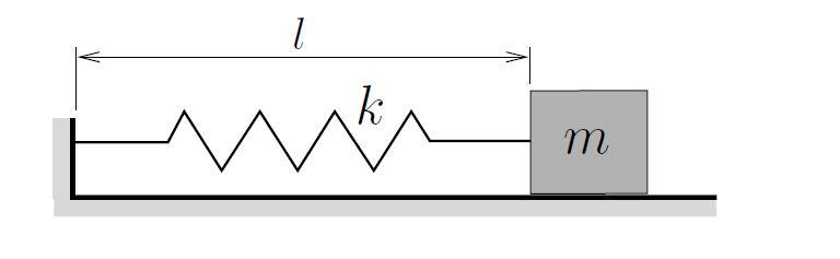
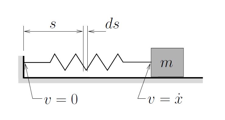
Begin by estimating the kinetic energy of the spring making some simplifying assumptions:
- The mass of the spring is uniformly distributed along the length of the spring.
- The velocity of any point on the spring is proportional to its distance from the fixed end.
Equivalent Stiffness – Stiffness and Flexibility Approaches
To determine the effective stiffness , it can similarly be shown that the potential energy of the system is
![\[U = \frac{1}{2} \bigl[k_{EFF} \bigr] q^2\]](https://engcourses-uofa.ca/wp-content/ql-cache/quicklatex.com-d81c0069ac297e402986ab802e965839_l3.png "Rendered by QuickLaTeX.com")
so that can also be found by inspection once the potential energy expression has been determined. However, there are also other approaches, stiffness and flexibility methods, that can be used to determine based on statics. These approaches are similar and are based on the idea that the force  applied to a system (in the positive coordinate direction) and the resulting deflection
  (of the coordinate) are related by
![\[F = k_{EFF} \, \Delta\]](https://engcourses-uofa.ca/wp-content/ql-cache/quicklatex.com-dada2c8c3a0d3e77e9ae93726808e3be_l3.png "Rendered by QuickLaTeX.com")
In the stiffness approach, the system is given a unit displacement and the force required to maintain this deformed configuration is determined through statics. The effective stiffness is then given by
![\[k_{EFF} = \frac{F}{1} = F\]](https://engcourses-uofa.ca/wp-content/ql-cache/quicklatex.com-31f5908bbd7a9b7e9a6b36886965219f_l3.png "Rendered by QuickLaTeX.com")
In the flexibility approach, a unit load is applied to the system and the resulting deflection is determined using statics. The effective stiffness is then given by
![\[k_{EFF} = \frac{1}{\Delta}\]](https://engcourses-uofa.ca/wp-content/ql-cache/quicklatex.com-dfeee4fea7954b862da6e05889145cc2_l3.png "Rendered by QuickLaTeX.com")
In both of these approaches it is important to realize that the force and the displacement are always measured in the positive coordinate direction. Also note that if the coordinate is a rotation (measured in radians), the same approach can be used replacing the force with a torque  . The details are summarized as follows.
For single degree of freedom systems, the process of finding the effective stiffness can be generalized as either a stiffness or flexibility approach, both of which are static in nature and are based on the definition
![\[\boxed{k_{EFF} = \frac{\text{Force applied in the direction of motion}}{\text{Displacement in the direction of motion}}}\]](https://engcourses-uofa.ca/wp-content/ql-cache/quicklatex.com-e7d82093cb718832108e143036601793_l3.png "Rendered by QuickLaTeX.com")
Stiffness Approach
Linear Displacements: Displace the system such that it has a unit displacement in the positive coordinate direction. Then, using statics, determine the force required in the positive coordinate direction to maintain this deflected state. Then, since  and
and  ,
,
![\[k_{EFF} = F\]](https://engcourses-uofa.ca/wp-content/ql-cache/quicklatex.com-1ac9c54514d892316a1bb4dc0fbc1cc2_l3.png "Rendered by QuickLaTeX.com")
Angular Displacements: Displace the system such that it has a unit angular displacement ( ) in the positive coordinate direction. Then, using statics, determine the torque required in the positive coordinate direction to maintain this deflected state. Then, since
  and ,
and ,
![\[\hat{k}_{EFF} = T\]](https://engcourses-uofa.ca/wp-content/ql-cache/quicklatex.com-8e98d6418c694991506b0729a549cc69_l3.png "Rendered by QuickLaTeX.com")
Flexibility Approach
Linear Displacements: Apply a unit load in the positive coordinate direction and determine, through statics, the resulting deflection in the positive coordinate direction. Then, since  and
and  ,
,
![\[k_{EFF} = \frac{1}{\Delta}\]](https://engcourses-uofa.ca/wp-content/ql-cache/quicklatex.com-933ba3fb2125f1051bdc12ab2141e426_l3.png "Rendered by QuickLaTeX.com")
Angular Displacements: Apply a unit torque in the positive coordinate direction and determine, through statics, the resulting angular deflection  in the positive coordinate direction. Then, since and
  ,
,
![\[\hat{k}_{EFF} = \frac{1}{\Phi}\]](https://engcourses-uofa.ca/wp-content/ql-cache/quicklatex.com-7f4621a1c28003615bcfb3e2735574b1_l3.png "Rendered by QuickLaTeX.com")
EXAMPLES
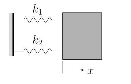
- Springs in Parallel
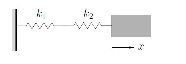
2. Springs in Series
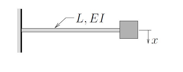
3. Mass at End of Cantilever (Lateral Motions)
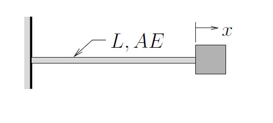
4. Mass at End of Cantilever (Axial Motions)
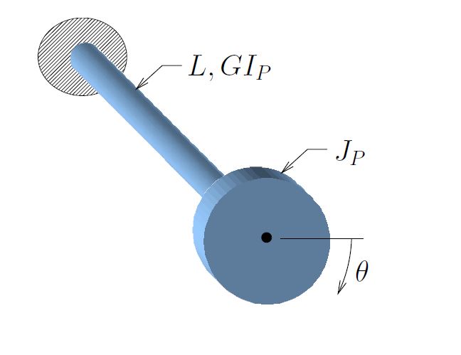
5. Mass at End of Cantilever (Torsional Motions)
Occasionally we need to modify these approaches slightly when a “unit” force or displacement would significantly change the geometry of the system resulting in a nonlinearity. In such cases we apply “small” forces or displacements instead of unit ones. Another way to think of this is to still apply a unit load, but the “unit” of the load is smaller (i.e. apply 1μN instead of 1 N). A similar approach could be taken for displacements.
EXAMPLE
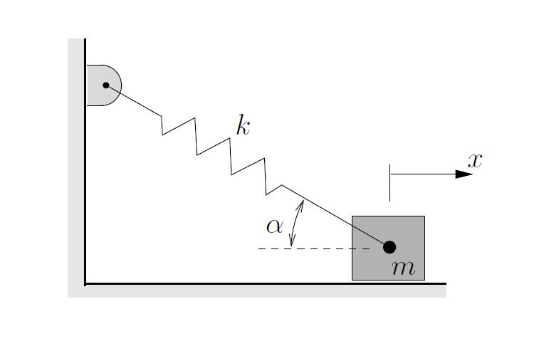
In the diagram below a spring supports a mass and makes an angle  with the direction of motion. Determine the effective stiffness of the spring in this situation. Assume that only small motions occur.
EXAMPLE
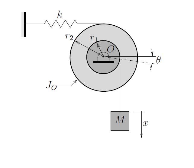
Determine the natural frequency for the system shown below. The double pulley set has a mass moment of inertia  about its center
  . A mass
  is supported by a light inextensible cable.
EXAMPLE
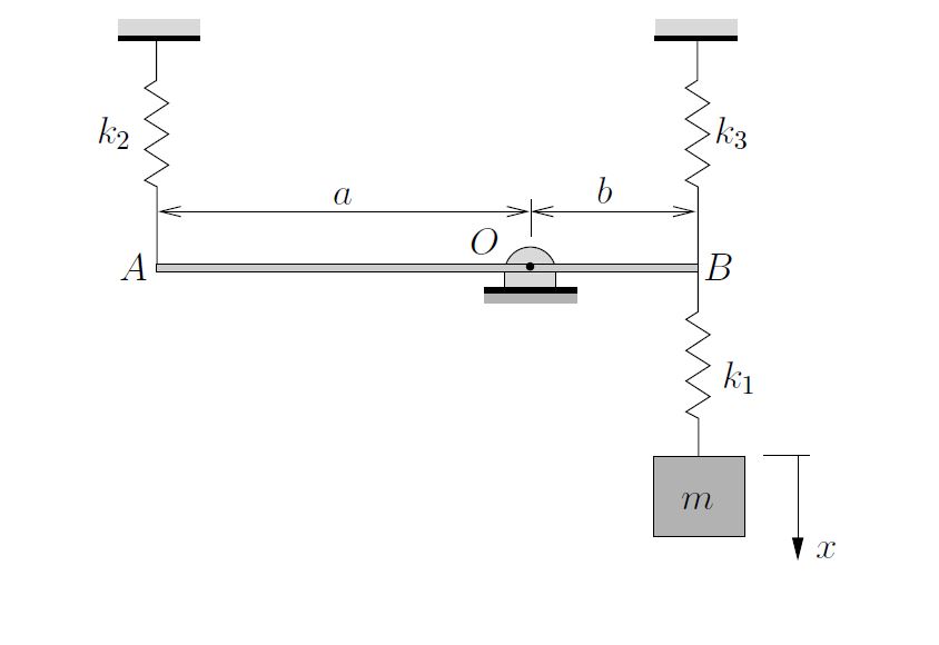
Determine the effective stiffness of the system shown below. Neglect the mass of the bar  .
.
EXAMPLE
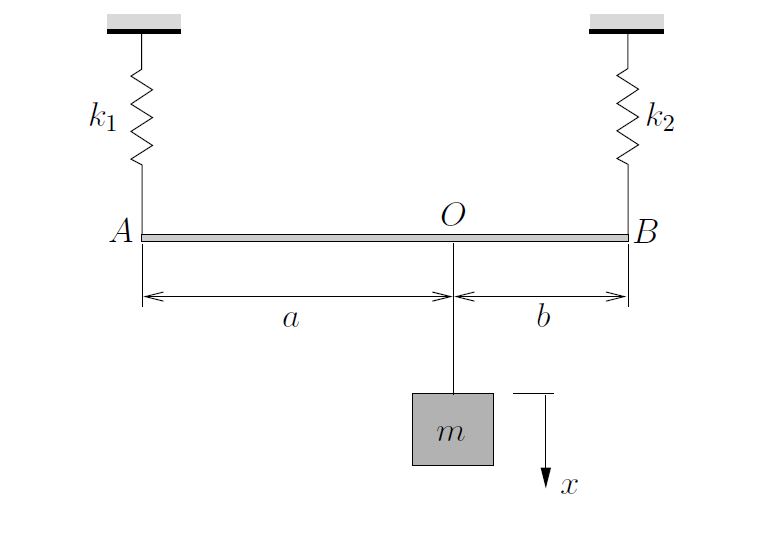
Determine the effective stiffness of the system shown below. Neglect the mass of the bar .
EXAMPLE
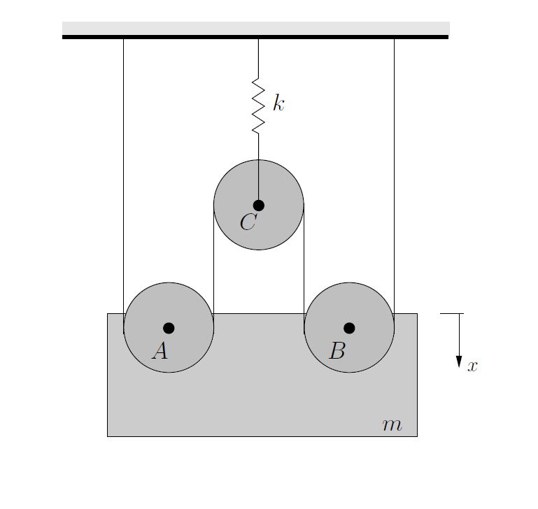
A block of mass  is supported by a cable and pulley system as shown below. Pulleys
  and
and  are pinned to the block while pulley
  is attached to a rigid support by a spring of stiffness
  . Neglecting the mass of the pulleys and treating the cable as inextensible, determine
- the effective stiffness of the cable and pulley system,
- the natural frequency of free vibrations.
EXAMPLE
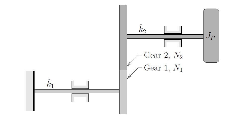
In the system shown below, a rotor with polar moment of inertia  is supported by a combination of shafts and gears as shown. Shafts 1 and 2 have torsional stiffnesses
  and
and  respectively while gears 1 and 2 have
  and
and  teeth respectively.
Determine the effective stiffness  for this system and the natural frequency of free vibrations. Neglect the masses of the gears.
Excellent