
Moments of Inertia of area: Rectangular moment of inertia
The moment of inertia of an area about an axis is a concept appearing in the formulations of several physical phenomena. The moment of inertia of an area is a geometric property of the area. Its value reflects how strong an object (i.e. stiffness) is against bending or twisting about some axis.
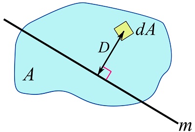
The mathematical definition of the moment of inertial of an area (two-dimensional region) about an axis is,
(10.1) ![\[I_m = \int_A D^2 dA\]](https://engcourses-uofa.ca/wp-content/ql-cache/quicklatex.com-b99a6bc7be3e7516d11eaf0e737aa8de_l3.png "Rendered by QuickLaTeX.com")
where  is the moment of inertia of the area about an axis
  in the plane of the area, and
  is the perpendicular distance from the axis m to the differential area
  as shown in Fig. 10.1. The axis is called the axis of rotation. The differential element, , in this definition, is infinitesimal (approaching to zero) in any directions on the plane. The value of depends on the location and direction of the axis, and the shape of the area. This quantity has the dimension of the length to the power of four (e.g.
  ).
).
The moment of inertia  is also called the second moment of area. The centroid of an area,
  , is called the first moment of area. The word moment is used because terms like
  meaning distance to an axis multiplied by an area are analogous to the definition of the moment of a force expressing distance to an axis multiplied by a force.
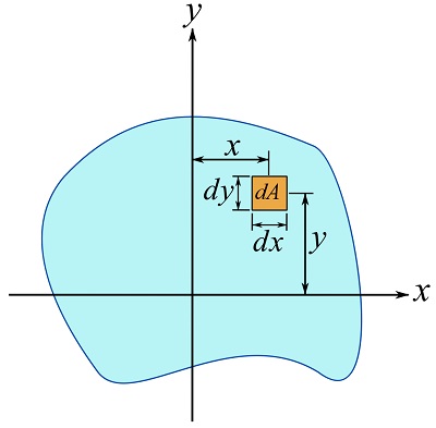
When the moment of inertia is calculated about two orthogonal axes in the plane of the area, it is called the rectangular moment of inertia. If x and y are two perpendicular axes (Fig. 10.2), the moments of inertia of an area about the x and y axes are denoted as  and
and  and determined by,
(10.2) ![\[\begin{split}I_x &= \int_A y^2 dA\\I_y &= \int_A x^2 dA\end{split}\]](https://engcourses-uofa.ca/wp-content/ql-cache/quicklatex.com-f9d370935c2df622787103005070a216_l3.png "Rendered by QuickLaTeX.com")
where  and
and  are squared distances from the differential area (infinitesimal in all directions) to the x and y axes respectively (i.e., the coordinates of the differential area).
The integration in Eqs. 10.2 can generally be evaluated using double integrals in a Cartesian coordinate system as,
(10.3) ![\[\begin{split}I_x &= \iint_A y^2 dxdy\\I_y &= \iint_A x^2 dxdy\end{split}\]](https://engcourses-uofa.ca/wp-content/ql-cache/quicklatex.com-06c8504f7309b0ba60ccdfc7d62c4a1e_l3.png "Rendered by QuickLaTeX.com")
where  is a differential element of area (in the Cartesian coordinate system) as shown in Fig. 10.2.
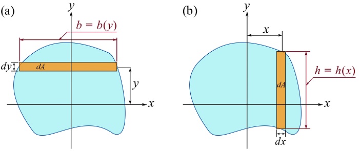
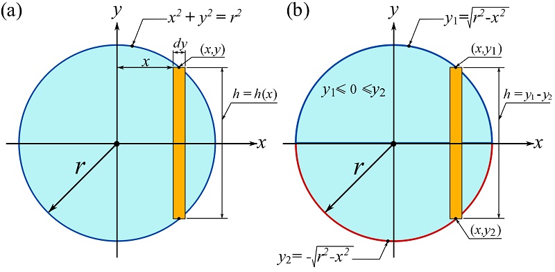
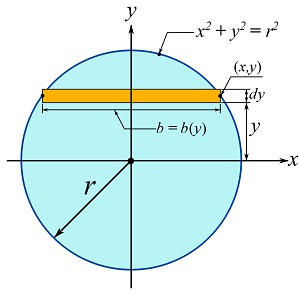
Alternatively, it is possible to skip the double integration by using differential strips, i.e. rectangular elements being differential only in one direction, and write the integrals as single-variable integrals. To this end, consider  . If
. If  , being a strip along the x axis as shown in Fig. 10.3a, then the integration can be written as,
(10.4a) ![\[I_x=\int_{y_1}^{y_2} y^2 bdy\]](https://engcourses-uofa.ca/wp-content/ql-cache/quicklatex.com-a572f418d8863617f32e3e6ff5c7b782_l3.png "Rendered by QuickLaTeX.com")
which is a single-variable integral. As shown in Fig. 10.3b, the width,  , of the strip can be a fixed length or a function of the integral variable y, i.e.
  . Note that since the strip is differential (infinitesimal) in the y direction, the distance,
  , from the x axis to this element is well-defined (i.e.
  as
as  approaching zero).
 , and (b) .
With the same approach, we can choose a strip along the y axis as shown in Fig. 10.3b, and let  . Therefore,
  can be written as,
(10.4b) ![\[I_y=\int_{x_1}^{x_2} x^2 hdx\]](https://engcourses-uofa.ca/wp-content/ql-cache/quicklatex.com-742fc9f67afc34aadd522946a1134e35_l3.png "Rendered by QuickLaTeX.com")
Note that in this case the height,  , of the strip is a function of x as
  , and is differential in the x direction.
Remark: as a general approach, differential strips are chosen to be parallel to the axis of rotation. If the strips are not parallel to the axis of rotation, the formulation is different. More details will be provided later.
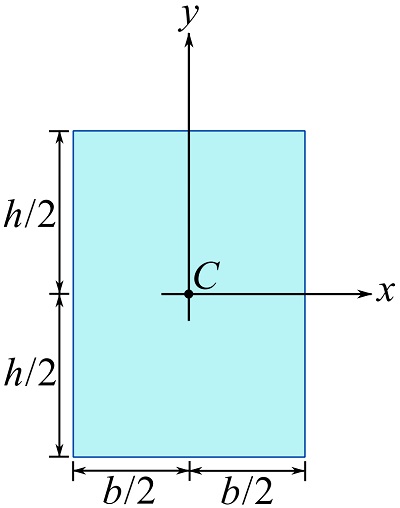
EXAMPLE 10.1.1
Determine the moment of inertia of a rectangular area about the axes crossing its centroid and parallel to its edges as shown.
SOLUTION
To calculate , consider a differential strip parallel to the x axis and with an area of as shown below.
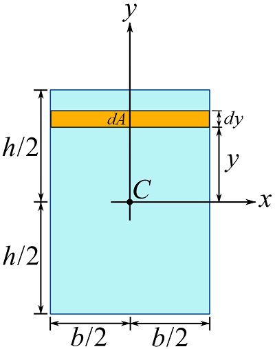
Using Eq. 10.4a, we can, therefore, write,
![\[\begin{split}I_x&=\int_{y_1}^{y_2} y^2 bdy=\int_{-\frac{h}{2}}^{\frac{h}{2}} y^2 bdy\\&=\frac{bh^3}{12}\end{split}\]](https://engcourses-uofa.ca/wp-content/ql-cache/quicklatex.com-788a854db4a8d46b9b432b121af8dd5d_l3.png "Rendered by QuickLaTeX.com")
Note that the limits of the integral are determined based on the position of the area in the chosen coordinate system.
To calculate , consider a differential strip parallel to the y axis and with an area of as shown below.
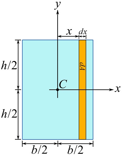
Therefore, Eq. 10.4b leads us to,
![\[\begin{split}I_y&=\int_{x_1}^{x_2} x^2 hdx=\int_{-\frac{b}{2}}^{\frac{b}{2}} x^2 hdx\\&=\frac{hb^3}{12}\end{split}\]](https://engcourses-uofa.ca/wp-content/ql-cache/quicklatex.com-4da3b9b1ca11b80c19d18d01bf0c916a_l3.png "Rendered by QuickLaTeX.com")
The moment of inertia depends on the axis about which it is calculated. Note that the axis of rotation can be outside the area.
For the sake of demonstration, the moment of inertia of a rectangular area about an axis running along its base is calculated in the following example.
EXAMPLE 10.1.2
Determine the moment of inertia of a rectangular area about the axes, x, along its based as shown. Compare the result with the result of Example 10.1.1.
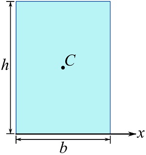
SOLUTION
Choose the differential strip shown and calculate Eq. 10.4a.
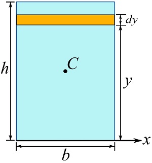
![\[\begin{split}I_x&=\int_{y_1}^{y_2} y^2 bdy=\int_{0}^{h} y^2 bdy\\&=\frac{bh^3}{3}\end{split}\]](https://engcourses-uofa.ca/wp-content/ql-cache/quicklatex.com-73b90607a0d0206fe61db4d2c003e009_l3.png "Rendered by QuickLaTeX.com")
As you can observe, the moment of inertia of a rectangular area about the axis along its base is  whereas it is
  if the axis is shifted to cross the centroid of the area.
The following examples delineate using differential strips to calculate the moments of inertia of a triangular and a circular area.
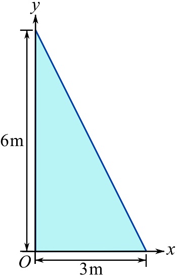
EXAMPLE 10.1.3
Determine the moment of inertia of the depicted triangular area about the x and y axes as shown.
SOLUTION
To calculate , consider a differential strip parallel to the x axis and with an area of such that is a (linear) function of y as shown below.
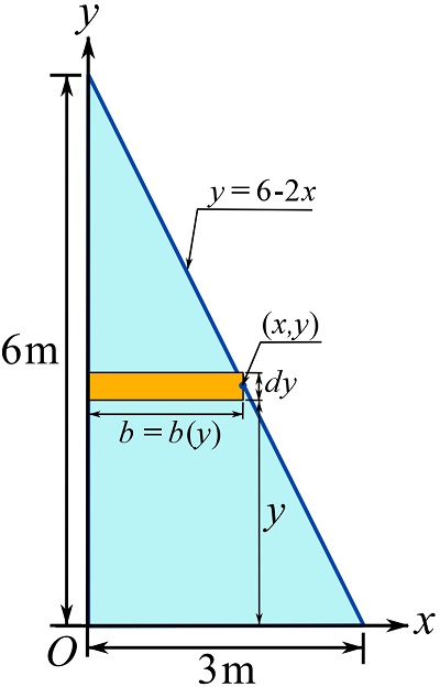
Using the equation of the line,  , we can write
  and therefore,
![\[b=\frac{6-y}{2}\]](https://engcourses-uofa.ca/wp-content/ql-cache/quicklatex.com-d9630c3e7cd5f3e2e1fbde4ab3074e7c_l3.png "Rendered by QuickLaTeX.com")
Consequently, we can calculate Eq. 10.4b as,
![\[\begin{split}I_x&=\int_{y_1}^{y_2} y^2 bdy=\int_0^6 y^2 (\frac{6-y}{2})dy\\&=54\text{ m}^4\end{split}\]](https://engcourses-uofa.ca/wp-content/ql-cache/quicklatex.com-94ea26da2d9c78eb6b06847dd8fa4ca3_l3.png "Rendered by QuickLaTeX.com")
To calculate , consider a differential strip parallel to the y axis and with an area of such that is a (linear) function of x as shown below.
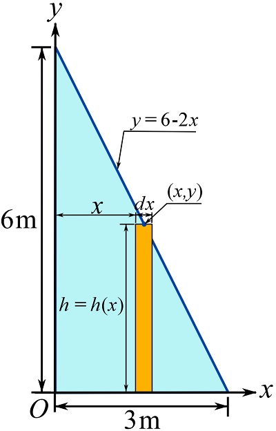
Therefore,  , and Eq. 10.4b becomes,
![\[\begin{split}I_y&=\int_{x_1}^{x_2} x^2 hdx=\int_0^3 x^2 (6-2x)dx\\&=13.5\text{ m}^4\end{split}\]](https://engcourses-uofa.ca/wp-content/ql-cache/quicklatex.com-23d8aa52e4df0fe10545f79b573601e1_l3.png "Rendered by QuickLaTeX.com")
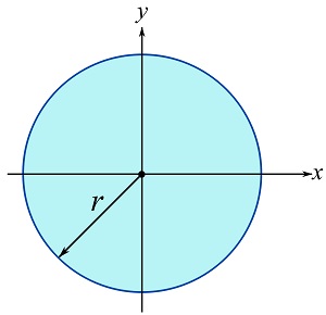
EXAMPLE 10.1.4
Determine the moment of inertia of a circular area about the y axes crossing the center (centroid) of the area as shown.
SOLUTION
Consider a vertical differential element with an area of  as shown in the figure. From the equation of the circle,
  , two functions as
  and
and  can be obtained (shown in the figure below). Since the strip is confined between these two functions, the height, , of the strip is
  (note that should be positive as it is the height of the element).
Therefore,
![\[\begin{split}I_y&=\int_{x_1}^{x_2} x^2 hdy=\int_{-r}^{r} x^2 (2\sqrt{r^2-x^2})dx\\&=2\left(\frac{r^4}{8}\arcsin (\frac{x}{r})+\frac{x}{8}(2x^2-r^2)\sqrt{r^2-x^2} \right)\Big|_{-r}^r\\&=\frac{\pi r^4}{4}\end{split}\]](https://engcourses-uofa.ca/wp-content/ql-cache/quicklatex.com-a2fe32a36790f09f0091ddafb686579b_l3.png "Rendered by QuickLaTeX.com")
Try to calculate for the circular area. You should consider a differential strip as shown below. You will observe that  for a circular area.
A physical application of the moment of inertia of an area: bending stiffness
The deformation of a beam under bending is directly related to its bending stiffness. In addition to other factors like the material and length of a beam, the bending stiffness directly depends on the moment of inertia of the beam cross section(s) perpendicular to the longitudinal axis of the beam. As an example consider bending of a lumber beam loaded by a single force as shown in Fig. 10.4. In case one, the beam is placed flat on the supports while it is vertically positioned in the second case. Under the same load, it is tangible that the bending beam deforms less in case 1 than in case 2. If the deformation is measured by the beam deflection,  , at its half length, we can observe that
  and
and  . This structural behavior is explained by the bending stiffness of the beam.
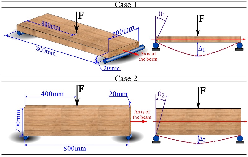
The bending stiffness is directly related to the moment of inertia of the beam’s cross section as shown in Fig. 10.5. For this cross section, the moment of inertia of its section (perpendicular to the beam axis) is about the axis crossing the centroid of the section; see Fig. 10.5. Presentation and proof of equations regarding bending stiffness is out of scope of this course.
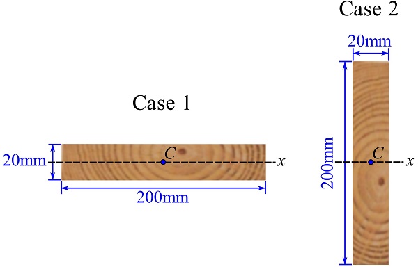
The moment of inertia of the beam section for each case is as follows.
Case 1:
![\[I_x=\frac{bh^3}{12}=\frac{(200)(20)^3}{12}=1.33\times 10^5 \text{ mm}^4\]](https://engcourses-uofa.ca/wp-content/ql-cache/quicklatex.com-842c6573997e19cb90bfe3181e6d266d_l3.png "Rendered by QuickLaTeX.com")
Case 2:
![\[I_x=\frac{bh^3}{12}=\frac{(20)(200)^3}{12}= 1.33\times 10^7\text{mm}^4\]](https://engcourses-uofa.ca/wp-content/ql-cache/quicklatex.com-ac82ba0d3f368d36672f1bdf031a4fda_l3.png "Rendered by QuickLaTeX.com")
Consequently, we can say that the beam in case 2 is 100 times stiffer in bending than the beam in case 1; qualitatively, bending the lumber beam positioned as in case 2 is much more difficult than bending the beam positioned as in case 1.