
Forces and Moments: Simplification of force and couple systems
Resultant moment
Resultant moment of the moments of forces
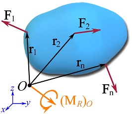
Like forces (vectors), moments can be added together to determine their collective effect known as the resultant moment. Let  be a system of forces acting on a body (Fig. 3.23). The resultant moment of the forces about a point
  (anywhere in the space) is determined by a vector addition of the moment of each force about ,
(3.23) ![\[(\bold M_R)_O=\sum_{i=1}^n \bold r_i\times \bold F_i \]](https://engcourses-uofa.ca/wp-content/ql-cache/quicklatex.com-b9d8c8a1b7ffb3ae05867a4718fe00a8_l3.png "Rendered by QuickLaTeX.com")
or in a concise notation,
![\[(\bold M_R)_O=\sum \bold r\times \bold F\]](https://engcourses-uofa.ca/wp-content/ql-cache/quicklatex.com-8409e2ddf8dcf69a2c78a3457ad11181_l3.png "Rendered by QuickLaTeX.com")
where  is the quasi-moment arm vector of
  , and
, and  is the resultant moment about point .
Remark: the resultant moment of forces is a moment acting about a point (or axis). This moment conveys the collective rotational tendencies of the forces about an specific point (or axis). Indeed, changing the location of the pivot point changes the resultant moment of the forces.
In the case of a coplanar (two-dimensional) force system, Eq. 3.23 reduces to an algebraic sum of the moments. In this case, the sign of the moments of the forces and their resultant follow the convention that associates a positive moment with a counterclockwise rotation.
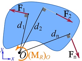
The resultant moment of a system of coplanar forces  about a point in the plane of the forces (Fig. 3.24a) is,
(3.24) ![\[(M_R)_O=\circlearrowleft{+}\sum_{i=1}^n F_id_i=\sum_{i=1}^n (M_O)_i\]](https://engcourses-uofa.ca/wp-content/ql-cache/quicklatex.com-de472e27e0ddd4182d3d91ac5f5bf064_l3.png "Rendered by QuickLaTeX.com")
where  are the magnitude of the forces,
  are the moment arms, and the notation
  indicates the direction of positive moments. The result of the equation is a scalar. If
  is positive, the sense of the rotation of the moment is counterclockwise, otherwise it is clockwise.
In a Cartesian coordinate system, decomposing each force to its rectangular components and adding the moments of the components of the forces (according to the principle of moments) facilitate calculating the resultant moment.
EXAMPLE 3.4.1
Calculate the resultant moment of the force system about point .
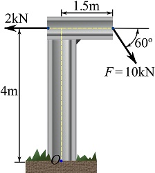
SOLUTION
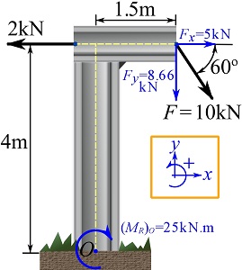
Setting the positive directions (shown in the figure), the rectangular components of the forces are determined.
The sum of moments of the components of the forces about point is,
![\[\begin{split}(M_R)_O&=\circlearrowleft{+} \sum Fd= (2)(4) -(5)(4)-(8.66)(1.5)=-25 \text{ kN.m}\\\therefore (M_R)_O&=-25 \text{ kN.m}\quad \text{or} \quad (M_R)_O=25\text{ kN.m}\circlearrowright\end{split}\]](https://engcourses-uofa.ca/wp-content/ql-cache/quicklatex.com-ed222eb998a15e17cb53808e80610a86_l3.png "Rendered by QuickLaTeX.com")
Resultant couple moment
If several couples (couples of forces) act on a body (Fig. 3.25), the couple moments can be added together to determine the resultant couple moment. Since the couple moments are free vectors (independent of location), their resultant is also a free vector. In a mathematical notation, the resultant of the couple moments  is,
is,
(3.25) ![\[\bold M_R=\sum_{i=1}^n \bold M_i \]](https://engcourses-uofa.ca/wp-content/ql-cache/quicklatex.com-7f7641a7f1c99d9657951dfd11e1bb50_l3.png "Rendered by QuickLaTeX.com")
where  is the resultant couple moment. The calculation of a resultant couple moment does not depend on a pivot point, therefore has no subscription denoting a pivot point. Equation 3.25 is a vector sum in general, however, it becomes a scalar sum in two-dimensional problems. The sign of a couple moment in two-dimensions is positive if it is counterclockwise.
Resultant Moment of a system of forces and couple moments
A system containing forces and couple moments acting on a body is referred to as a system of forces and couple moments or a force-couple system.
If forces and couple moments act on a body, the resultant moment of the forces and couple moments about a point is defined as the sum of the moments of the forces about in addition to the sum of the couple moments. In a mathematical notation,
(3.26) ![\[(\bold M_R)_O=\sum_{i=1}^n \bold r_i\times \bold F_i + \sum_{i=1}^n \bold M_i \]](https://engcourses-uofa.ca/wp-content/ql-cache/quicklatex.com-95b275ff95c22095c7b162f03d5c9aab_l3.png "Rendered by QuickLaTeX.com")
or in a concise notation,
![\[(\bold M_R)_O=\sum \bold r\times \bold F + \sum \bold M\]](https://engcourses-uofa.ca/wp-content/ql-cache/quicklatex.com-afd09a1f4a021862deab81e8200a990a_l3.png "Rendered by QuickLaTeX.com")
This definition physically conveys the rotational tendencies produced by the forces about the pivot point plus the rotational tendencies of the couple moments produced on the body.
and simplification of systems
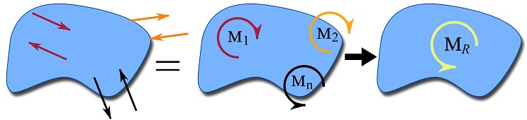
A force-couple system can be reduced or simplified to an equivalent system that consists of only a resultant force and a resultant couple moment, or even a single force, applied at a specific point of the body (or space). The reduction of forces and moments simplifies the analysis of the system in question.
A simplified system makes it convenient to quickly observe and understand the overall disclosure of a force-couple system on the body. For example, each limb of a human body has its own weight, but it is convenient and more understandable (in many problems) to consider the total weight and shown it as a single force on the body rather than showing each limb’s weight. In this section, the concept of equivalent force-couple systems is first defined and then simplification of different force-couple systems are presented.
Equivalent systems
Two force-couple systems are called equivalent if their external effects on a rigid body are the same. The following two conditions needs to be satisfied.
1- The resultant forces of the two systems are equal, i.e.,
![\[\underset{\text{System 1}}{\bold F_R}=\underset{\text{System 2}}{\bold F_R}\implies \sum_\text{System 1}\bold F=\sum_\text{System 2}\bold F\]](https://engcourses-uofa.ca/wp-content/ql-cache/quicklatex.com-10a04e15d7225a5b2e6392dda1d82b56_l3.png "Rendered by QuickLaTeX.com")
2- The resultant moments of the systems about any fixed arbitrary point, , in the space are equal, i.e.,
![\[\underset{\text{System 1}}{(\bold M_R)_O}=\underset{\text{System 2}}{(\bold M_R)_O}\implies\sum_\text{System 1}\bold r\times \bold F+ \sum_\text{System 1} \bold M=\sum_\text{System 2}\bold r\times \bold F+ \sum_\text{System 2} \bold M\]](https://engcourses-uofa.ca/wp-content/ql-cache/quicklatex.com-e780303514e576b2828ab7cbbf0f732f_l3.png "Rendered by QuickLaTeX.com")
Note that the resultant moment of a system is the sum of moments produced by the system forces about a fixed point plus the couple moments.
Context: Simplification of force and couple systems
- Engineers often simplify systems by combining forces and moments to make calculations easier.
- When simplifying systems, engineers need to ensure that the simplified system has external effects equivalent to the original system.
- This approach is effective for determining support reactions as part of rigid body equilibrium (Section 5.2), particularly in structures subject to many combinations of point forces and/or structures subject to distributed loads (Section 3.5).
- This simplification approach is limited as it may not allow internal effects (e.g. tension, shear) in a member to be assessed. Internal effects are discussed more in Chapter 7 of this book.
Applications: Where do engineers use simplifications of force and couple systems?
In addition to designing new structures, engineers also evaluate existing structures in case they are being changed to resist different types of loads or if they are degrading because of problems like corrosion. Looking at the column in Fig. 3.26, we see that forces are transferred into the column from a few sources including the steel beams resting on the column ledges (formally called ‘corbels’) as well as forces and moments coming from the above floor.
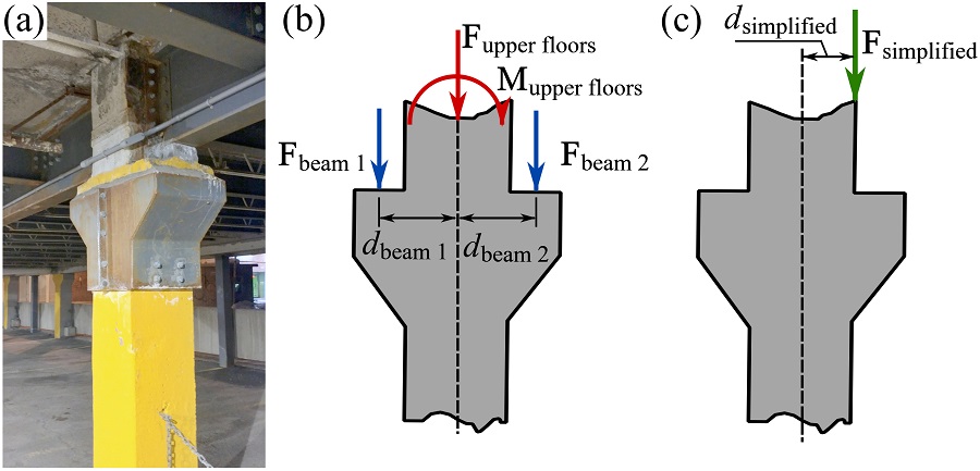
If you were to check this column’s adequacy at resisting the applied forces without failing the easiest approach is to reduce the system to a single force,  , acting at an eccentricity,
  . With these simplified forces, you can compare these forces to the material capacity of the column accounting for the combination of forces and moments. Engineers often use design resources (e.g. tables and charts) that allow them to quickly evaluate the adequacy of these simplified systems. Material capacities and these design resources are discussed in upper year engineering courses.
EXAMPLE 3.4.2
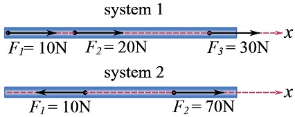
Consider two systems of non-equal but collinear forces (acting on the same bar) as shown in the figure. Show that both systems are equivalent.
Solution
1- The same resultant forces.
![\[\begin{split}\text {system 1: } F_R&=\overset{+}{\rightarrow}\sum F_x= 10+20+30=60\text{ N}\\\text {system 2: } F_R&=\overset{+}{\rightarrow}\sum F_x= 70 -10=60\text{ N}\\\therefore \underset{\text{System 1}}{\bold F_R}&=\underset{\text{System 2}}{\bold F_R}\end{split}\]](https://engcourses-uofa.ca/wp-content/ql-cache/quicklatex.com-6e600e48483b6c449b920bbd484fc4d6_l3.png "Rendered by QuickLaTeX.com")
2- The same resultant moments.
Selecting a point on the line of action of the forces leads to zero resultant moments for both systems.
Therefore the two force-couple systems are equivalent.
EXAMPLE 3.4.3
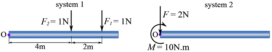
Prove that the coplanar force-couple systems shown in the figure are equivalent.
1- The same resultant forces.
![\[\begin{split}\text {system 1: } F_R&=+\uparrow\sum F_y= -1 -1=-2 \implies F_R=2 \text{ N}\downarrow\\\text {system 2: } F_R&=+\uparrow\sum F_y= -2 \implies F_R=2 \text{ N}\downarrow\\\therefore \underset{\text{System 1}}{\bold F_R}&=\underset{\text{System 2}}{\bold F_R}\end{split}\]](https://engcourses-uofa.ca/wp-content/ql-cache/quicklatex.com-8eb11a6846c979e32807a44dc000349c_l3.png "Rendered by QuickLaTeX.com")
2- The same resultant moments.
The resultant moments of both systems about an arbitrary point should be equal. We choose point on right end of the bar and calculate the resultant moments.
![\[\begin{split}\text {system 1: } (M_R)_O&= \circlearrowleft{+}\sum Fd= -(1)(4) -(1)(6) = -10\text { N.m}\\\implies (M_R)_O&=10\text { N.m}\circlearrowright\\\text {system 2: } (M_R)_O&= \circlearrowleft{+}\sum Fd + \sum M= (2)(0) -10 = -10\text { N.m}\\\implies (M_R)_O&=10\text { N.m}\circlearrowright\\\therefore \underset{\text{System 1}}{(\bold M_R)_O}&=\underset{\text{System 2}}{(\bold M_R)_O}\end{split}\]](https://engcourses-uofa.ca/wp-content/ql-cache/quicklatex.com-06606632650377654d78b535c6568418_l3.png "Rendered by QuickLaTeX.com")
Therefore the systems are equivalent.
In the last example, we observe that a system of two forces is equivalently represented by a system of one force and a couple moment. Any system can be simplified to a system including only a force and a couple. This concept is presented in the next subsection.
The concept of equivalent systems can be used to simplify or reduce a force-couple system to an equivalent system that generally includes only a resultant force and a resultant couple moment at one specific point. This process is called the simplification of a force-couple system.
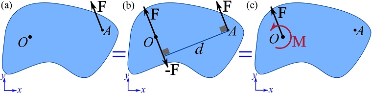
The following example shows how to move a force to a different application point without changing its external effect on the same rigid body. Consider a force  in the x-y plane as shown in Fig 3.27a. The force is acting at point
  . We intend to find an equivalent system in which acts at (or relocated to) point .
We can add (place) both and  to the at point without changing the original system (Fig. 3.27b); because
  . The system of forces shown in Fig. 3.27b indicates that at and at form a couple and can be replaced by a couple moment with the magnitude
  . The couple moment is a free vector and can be placed anywhere; we choose to locate it at point (Fig. 3.27c). The resultant system as shown in Fig. 3.27c is an equivalent system consisting of a force and a couple moment.
Upon relocating , the added couple moment with the magnitude is added (Fig. 3.27c). This states that if a force is relocated from point to point (not on the line of action of the force), a couple moment  should be added to the equivalent system to preserve the moment that the force in the original system creates about point .
 to point .
The general procedure of the simplification of a force-couple system to an equivalent system has the following steps:
- Choose a point, , on the body (or in the space) for all forces to be relocated there.
- Calculate the resultant moment of the forces about point and the couple moments, i.e.
 .
. - Move all the forces to the new location () and calculate the resultant force
 .
. - Place, at , a couple moment equal to .
Remark: to relocate a force from point to a new point , whenever visualization of forces are convenient (like in coplanar systems), you can first show the forces and at point . Then, create a couple moment using at and at , and show the couple moment together with at .
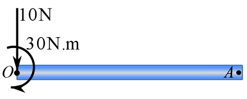
EXAMPLE 3.4.4
Reduce (simplify) the following system to an equivalent system consisting of a force and a couple moment acting at point .
The following steps are take.
1- Calculate the resultant moment of the forces about point and the couple moments, i.e.  (scalar formulation in two dimensions).
![\[\begin{split}(M_R)_O&= \circlearrowleft{+}\sum Fd + \sum M= -(2)(1.5) -(2)(2.5) -(2)(3.5) -(2)(4.5) - (2)(5.5) + 5\\&= -30\text { N.m}\end{split}\]](https://engcourses-uofa.ca/wp-content/ql-cache/quicklatex.com-8a3bbfae5242f7bf229fddde2c8ab513_l3.png "Rendered by QuickLaTeX.com")
The negative sign of  means the resultant moment is clockwise. Therefore,
![\[(M_R)_O=30\text { N.m} \circlearrowright\]](https://engcourses-uofa.ca/wp-content/ql-cache/quicklatex.com-5c339a69f4d9cc86fff779b577155be9_l3.png "Rendered by QuickLaTeX.com")
2- Calculate the resultant force  (scalar formulation in two dimensions).
![\[\begin{split}F_R=+\uparrow\sum F\implies F_R&=-2-2-2-2-2=-10 \text { N}\\\therefore \ F_R&=10 \text { N} \downarrow\end{split}\]](https://engcourses-uofa.ca/wp-content/ql-cache/quicklatex.com-567718875dfa836fbee65f883454341a_l3.png "Rendered by QuickLaTeX.com")
3- Place, at , the resultant force  and a couple moment equal to .
Although all systems can be reduced to an equivalent system consisting of a force and a couple moment, there are systems that can be further reduced to a single resultant force or a wrench as presented below.
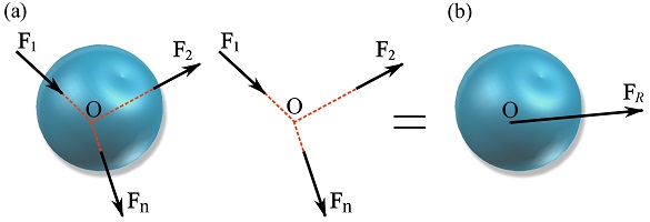
1- Concurrent force systems
In a concurrent force system (Fig. 3.28a), the lines of action of the forces meet (intersect) at a common point . Therefore, the forces produce no moment about and the system can be reduced to an equivalent system consisting of one resultant force as shown in Fig. 3.28b.
2- Coplanar force systems
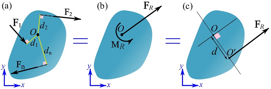
In a coplanar force system (Fig. 3.29a), the lines of action of the forces are in the same plane, say x-y plane. The moments of the forces about any point on the plane are perpendicular to the plane, so are their resultant moment. This system can be initially reduced to a resultant force located at any point and a resultant couple moment,  of the forces about point (Fig. 3.29b).
Then, the system can be further simplified to a system that contains only as shown in Fig. 3.29c. This is achieved by offsetting in the plane by distance  from (Fig 3.29c). Offsetting the force can replicate the same moment, , about point . This leads to a further simplified system shown in Fig. 3.29c.
To find , the resultant moments of the systems shown in Fig. 3.29b and c must be equal. Choosing point and using the scalar formulation, we write,
![\[\begin{split}\underset{\text{System b}}{(M_R)_O}&=\underset{\text{System c}}{( M_R)_O}\implies M_R = F_Rd\\\therefore d&=\frac{M_R}{F_R}\end{split}\]](https://engcourses-uofa.ca/wp-content/ql-cache/quicklatex.com-b93b0512586d7b27f3b3cb9d94eb26cb_l3.png "Rendered by QuickLaTeX.com")
It should be noted that should be offset in the correct side of , in order to replicate the couple moment (). This means that at its final location,  , should create a moment that is equal to about .
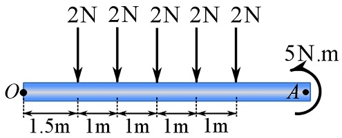
EXAMPLE 3.4.5
Reduce (simplify) the system of coplanar forces to a system consisting of a single resultant force. Measured from point , determine , the location of the resultant force.
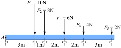
SOLUTION
1- Calculate  .
.
![\[\begin{split}F_R=+\uparrow\sum F\implies F_R&=-10-8-6-4-2=-30 \text { N}\\\therefore \ F_R&=30 \text { N} \downarrow\end{split}\]](https://engcourses-uofa.ca/wp-content/ql-cache/quicklatex.com-7e7c46a14566da445a30621904180d0d_l3.png "Rendered by QuickLaTeX.com")
2- Make the resultant moments of the original and the simplified systems equal.
![\[\begin{split}\text {Original system } (M_R)_A&= \circlearrowleft{+}\sum Fd= -(10)(3) -(8)(4) -(6)(6) -(4)(8) -(2)(11)\\&= -152\text { N.m}\end{split}\]](https://engcourses-uofa.ca/wp-content/ql-cache/quicklatex.com-7fff76a9d3ca1e5b87835d979aaf2b7b_l3.png "Rendered by QuickLaTeX.com")
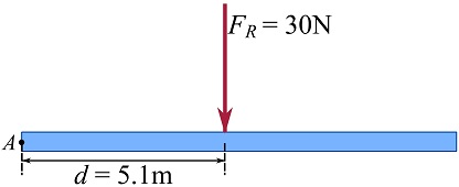
The negative sign of  means the resultant moment is clockwise. Therefore, the downward resultant force should be right to the rotation point to replicate such a moment. Therefore,
![\[\begin{split}\text {Original system } (M_R)_A&= 152\text { N.m} \circlearrowright\\\text {Simplified system } (M_R)_A&= \circlearrowleft{+} F_Rd= -(30)(d)\text { N.m}\\&\implies F_Rd= (30)(d)\text { N.m}\circlearrowright\end{split}\]](https://engcourses-uofa.ca/wp-content/ql-cache/quicklatex.com-d164fc6cd32591143518943ada49a5e3_l3.png "Rendered by QuickLaTeX.com")
Letting  leads to,
![\[d = \frac{152 \text{ N.m}}{30 \text{ N}}=5.1\text { m}\]](https://engcourses-uofa.ca/wp-content/ql-cache/quicklatex.com-321509c92bf03bc5c0e5e2b726bc6ec3_l3.png "Rendered by QuickLaTeX.com")
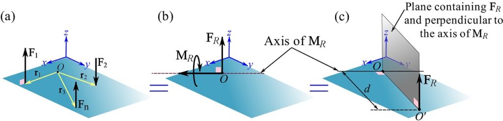
3- Parallel force systems (non-coplanar)
A parallel force system contains forces that are parallel to each other, say along the  axis as shown in Fig. 3.30a. Parallel forces can be slid to a common perpendicular plane like the x-y plane in this case (Fig 3.30a). A system of parallel forces can be initially simplified to a system consisting of a resultant force applied at a point in the x-y plane, and a resultant couple moment as shown in Fig. 3.30b.
Since all forces are parallel, is parallel to the axis. Also, all moments of the forces are perpendicular to the axis and therefore is perpendicular to the resultant force.
Similar to the further simplification of a coplanar system, where and are perpendicular, a system of parallel forces can be further reduced to a single resultant force (Fig. 3.30c). To achieve this, should be offset (to point ) in the plane containing and perpendicular to the axis of as shown in Fig 3.30c. The offset distance from is determined as,
![\[d=\frac{M_R}{F_R}\]](https://engcourses-uofa.ca/wp-content/ql-cache/quicklatex.com-897bc0fa257d3bf27780ecc09903f8c3_l3.png "Rendered by QuickLaTeX.com")
where  and
and  . It should be noted that the should be offset in the correct side of in order to replicate about .
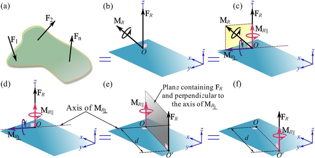
4- Systems reducing to a wrench
A general force-couple system in three dimensions (Fig. 3.31a) can be reduced to an equivalent system (Fig. 3.31b) consisting of a resultant force at a point and a resultant couple moment  .
.
Since and are not generally perpendicular to each other (as in a case of a parallel force system), the system cannot be further reduced to a single resultant force. However, this system can be further simplified to an equivalent system called a wrench. To achieve this, is resolved into components parallel and perpendicular to the resultant force . The components of are shown in Fig. 3.31c.
The parallel component ( ) and perpendicular component (
 ) of can be obtained using the dot product as (see Section 2.6.4),
![\[\bold M_{R\parallel}=(\bold M_R \cdot \bold u_{F_R})\bold u_{F_R},\quad \bold M_{R\perp}=\bold M_R - \bold M_{R\parallel}\]](https://engcourses-uofa.ca/wp-content/ql-cache/quicklatex.com-df94b8f03a3ff170419d41c481a6bd30_l3.png "Rendered by QuickLaTeX.com")
where  is the unit vector of .
For the purpose of clear visualization, and the components of are demonstrated in Fig. 3.31d.
Since and are perpendicular to each other, offsetting in the plane containing and perpendicular to can replicate . As demonstrate in Fig 3.31e, offsetting to point by distance  , where and
  , reduces the system to and as shown in Fig. 3.31f.
This final reduced system is called a wrench or screw as it resembles screwing which needs a simultaneous use of force and couple moment.
Videos
Force Reduction – Moment Couple System;
Force Reduction – Single Force Without Moment:
Force Reduction – Wrench: