
Engineering Mechanics: Statics: Free Body Diagram
A body is a physical object; it can be anything from a building, car, bolt, or even a piece of another body for example, a piece of a cable or any other structures.
To analyze the forces on a body and their effects, one technique is to imaginarily isolate the body from its surroundings, i.e. other bodies. In engineering mechanics, an isolated body is referred to as a free body. A free body and its surroundings interact by exerting forces and/or couple moments on each other.
The force/couple moment interactions between a free body and its surroundings obey Newton’s third law of motion. The law states that if a body exerts a force (and/or a couple moment) on a second body (the surroundings), then the second body exerts a force (and/or a couple moment) with the same magnitude but opposite direction on the first body.
the scope and shape of a free body depends on our intention about the part that we want to study. Some examples are:
The scope and shape of a free body depends on our intention about the part that we want to study. Some examples are
- If we consider the earth as a free body (a particle in fact) then the rest of the things in the universe are its surroundings.
- A building (isolated from the earth) is a free body and the earth is in its surroundings.
- A part of a cable under tension is a free body and the rest of the cable is in its surroundings.
The forces external to a free body exerted by its surroundings are referred to as external forces. The external forces can act on the outline (outer surface) or at internal points of a body. For example, the effects of gravitational, electrical or magnetic fields exert external forces at internal points of a body. A graphical demonstration of a free body subjected to external forces is referred to as a free-body diagram (FBD).
In addition to the external forces on a (free) body, there are internal forces within the (free) body. The internal forces are forces between the particles of a body. We will learn more about the resultants of internal forces in chapter 7. These forces do not appear (or affect) a FBD as they are inside the body itself and not externally exerted by the surroundings. Based on the way a body is chosen, three scenarios can be considered for constructing the FBD of a body:
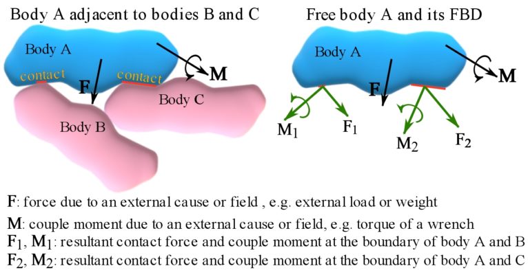
1- A single body. A body is surrounded and physically attached or in contact with a group of adjacent bodies. To construct the FBD, the body is isolated from its contact points (regions) with the adjacent bodies, and the contact forces and couple moments are shown on the body. These forces, called contact forces, are due to the contact interactions between the bodies. Sometimes, a body adjacent to another body is implicitly considered and its presence is expressed by its effects on the free body. For example, field forces, like the weight of the object. the effects of wind (surroundings) on a building (body) are wind forces to be considered on the walls of the building. An external force (or a distribution of force) originating from an implied adjacent body and acting on a free body can be referred to as a load. Figure 4.1 shows the FBD of a body in contact with other adjacent bodies. Note that the body and its adjacent bodies mutually exert forces on each other (according to Newton’s third law).
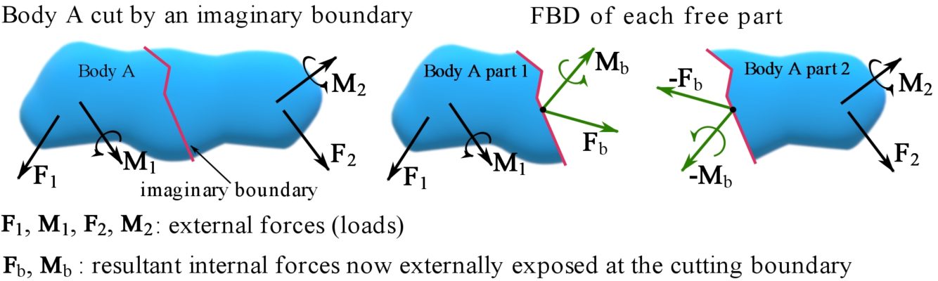
2- A part of a body. A body is imaginarily separated or cut (or sectioned) into two parts where either part is considered a free body. This creates an imaginary boundary isolating. This creates an imaginary boundary isolating the free body from the rest of the body. Thereby, the two parts can be considered adjacent bodies and the FBD of the body in focus follows the scenario of adjacent bodies (seen in the previous paragraph). The forces and couple moments at the imaginary boundary are in fact the internal forces of the original body. Because each part of the body can be considered a free body, each part becomes external to the other part. Therefore, the internal forces and couple moments at the imaginary boundary become external forces and couple moments in the FBD of each part considered separately. Figure. 4.2 shows the FBD of each part of a body imaginarily cut into two parts. Note that the external forces and couple moments at the separating boundary of each part follow Newton’s third law.
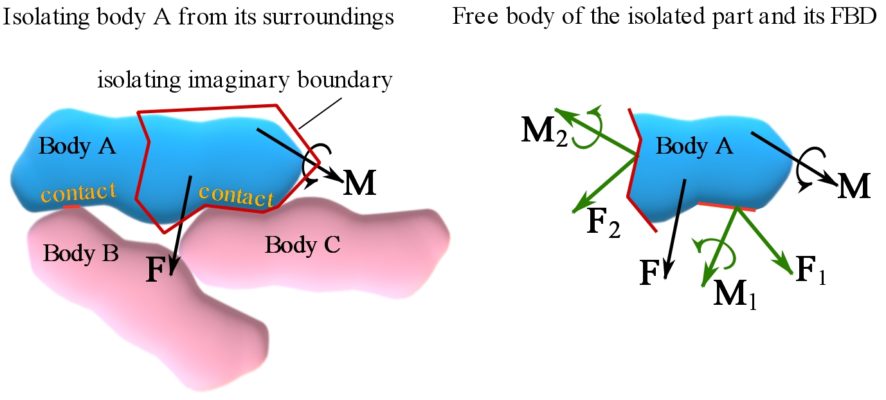
3- A group of bodies and parts. A body is to be isolated from other adjacent bodies and from a part of itself. The FBD must include the contact forces and couple moments, and internal forces and couple moments (exposed externally) at the boundaries with the adjacent bodies and the boundaries cutting the body. Fig. 4.3 shows the FBD of the body in this case.
The third scenario implies that a body or part of a body can become a free body if it is separated from its surroundings by imaginary boundaries.
Remark: a body does not need to be a single object. A group of bodies can be considered as a body. For example, a car has thousands of parts; each part is a body, and all parts together is a body as well. Each single part has a FBD and all parts grouped as a body has its own FBD.
Two simple examples of FBDs
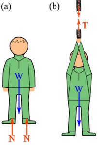
If you consider yourself as a body standing on the surface of the earth (surroundings), two forces act on you (Fig. 4.4a). The first is your weight,  (gravitational force from the earth), and the second the force that you feel on the sole of your feet. This is the reaction force
  , from the eliminated surroundings (earth), acting on the sole of your feet.
You are now gripping a rope while hanging from it; you feel the tension in your arms (Fig. 4.4b). The same tension exists inside the rope. If the rope is imaginarily cut at any point, isolating you and some part of the rope, then the FBD of the free body including you and the part of the rope has two forces: your weight, and the tension force,  inside the rope. The tension force is the internal force of the rope, now externally exposed in the FBD. Note that it is assumed that the weight of the part of the rope in the free body is negligible (zero).
Forces along special bodies
The first step toward finding and analyzing the forces on a body is drawing (demonstrating) its FBD. For some special types of bodies, their shapes, types of connections to their adjacent bodies, and the nature of external loads on them provide some information on the directions of internal forces of the bodies. Internal forces of two common structural members are discussed in this section. There are other structural members that will be discussed in future chapters.
Linearly elastic axial springs
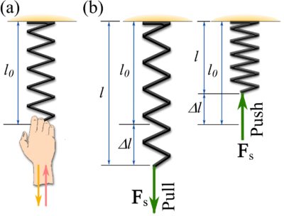
An axial spring is a spring (Fig. 4.5a) that can only be stretched or compressed. The spring produces a reacting pulling force if pulled, and it produces a reacting pushing force if pushed. This can be perceived by pulling or pushing on a spring. The pulling or pushing force that your hand feels is the force produced by the spring. According to Newton’s third law, the force by the spring on your hand is equal to the force by your hand on the spring (Fig. 4.5a).
The force produced by the spring equals the internal force of the spring and it is directed along its axis (length). This force is referred to as the spring force denoted by  . A spring force can be either a pulling force, called tension, or a pushing force, called compression.
Tension is produced when the spring elongates (by pulling) and compression is produced when the spring is compressed (by pushing). This implies that the spring force depends on the change of the length of the spring, or in other words the deformation of the spring (Fig. 4.5b). For a special kind of spring, called linearly elastic axial spring, the magnitude of the spring force is linearly proportional to its deformation. The word elastic means that the spring retrieves its original form once unloaded.
If the deformation of a linearly elastic spring is expressed as  where
where  is the original unloaded (unreformed) length of the spring and
  is its current (deformed) length, the spring force is formulated as,
(4.1) ![\[F_s=k\Delta l\]](https://engcourses-uofa.ca/wp-content/ql-cache/quicklatex.com-b46d38cae2180fc725870a913771c0c5_l3.png "Rendered by QuickLaTeX.com")
where  is the spring force,
  is the proportionality constant called the stiffness or constant of the spring. The force vectors pulling and compressing a spring are shown in Fig. 4.5b.
Remark: the nature of an axial spring determines that the spring has only one internal force with its line of action being along the axis of the spring.
Ropes, Cables, and pulleys
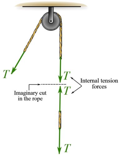
Ropes and cables only resist tension, meaning they can only be pulled. The rope or cable exposed internal force at any cut acts away from the member and in the direction along the straightened member. The internal force of a rope is shown in Fig. 4.6.
The direction of a rope or a cable can be changed by using a pulley to transfer its pull in a desired direction (Fig. 4.6). An ideal pulley is frictionless and does not affect the internal force of a rope or cable.
Support reactions
As previously mentioned, the FBD of a body (e.g. structural member) adjacent to other bodies depends on how the body is connected to the adjacent bodies. The physical conditions at a connection point (or region) of a body with the adjacent bodies are referred to as the support or connection. Based on the physical design, a support restrains certain translations or rotations of the body at the point of support or connection, by exerting forces or couple moments in the directions opposite to the translations or rotations. The support reactions should be considered in a FBD of a free body isolated from its supports. Support reactions may be unknown in a FBD, however, the types and sometimes the directions of the support reactions can be determined.
The general rule to determine the types and the directions of support reaction is: A support produces a force or a couple moment respectively in the direction of the translation or the rotation restrained by the support.
Support reactions can separately be discussed for two- and three-dimensional force systems.
Coplanar force systems (two dimensions)
In coplanar force systems, the forces (external and internal) are in the same plane and the couple moments are perpendicular to the plane producing only planar translations and rotations. A support or connection in a coplanar force system can affect planar translations and planar rotations. In these systems, there is no force causing motion in the third dimension. Three common support reactions are explained as follows.
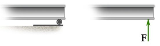
1- A roller support.
A roller support can be seen as a frictionless cylinder. A beam resting on a roller at one end as shown in Fig. 4.7 cannot translate in the direction perpendicular to the ground that is supporting the cylinder. The support prevents such translation by exerting a force in the opposite direction – a support reaction (Fig. 4.7).
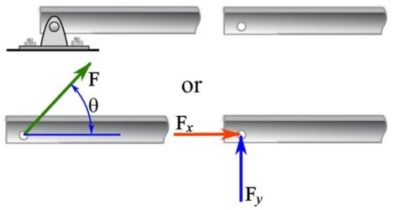
2- A pin or hinge support.
A pin (or a hinge) support prevents translation in any direction but allows rotation without friction. This kind of support can be physically applied to an end of a beam by passing a pin through a hole in the beam as shown in Fig. 4.8. The support reaction of a pin is a force in a particular direction measured by an angle from a reference axis like the axis of the beam (Fig. 4.8). This angle is unknown and depends on how the beam is loaded. Alternatively, the support reaction can be split into two perpendicular components as shown in Fig. 4.8, resulting  . Considering the x and y components of the support reaction implies that the support prevents the end of the beam from translating in both x and y direction.
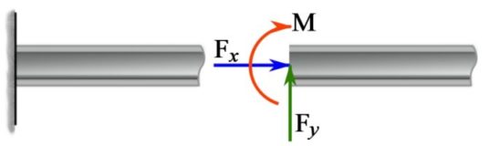
3- A fixed support.
A fixed support applied at an end of a beam restrains both the translation and rotation of the end (Fig. 4.9). Therefore, the support must exert a force and a couple moment to prevent the end of the beam from translation (in any direction) and rotation respectively.
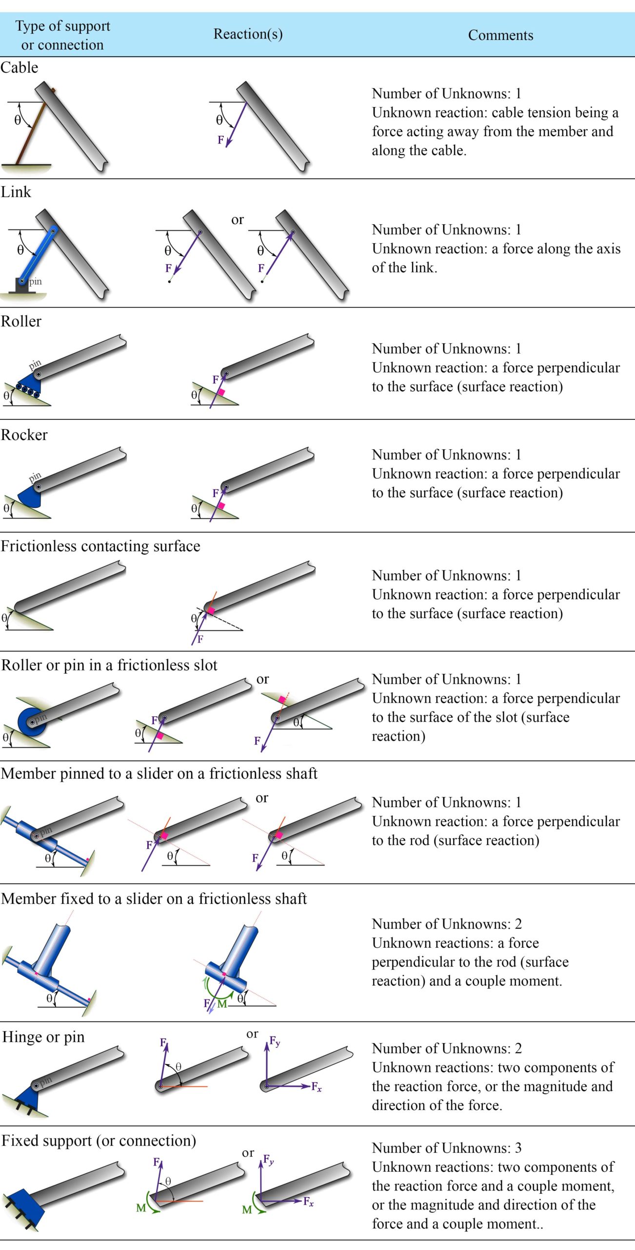
In general, a body in a coplanar force system can have translations in two directions and in-plane rotation. A support at a point of the body restrains the translation of the body at that point and/or the rotation of the body about that point by producing an opposing force or a couple moment. There are other types of supports or connections, some are shown and explained in Table 4.1.
Context: Supports
- A rigid body must be supported to prevent undesired movement when external loads are applied.
- Forces exerted by supports to prevent motion of a rigid body when external forces are applied are called reactions.
- Support conditions are idealizations of real-world situations. In real life, supports do not behave exactly as they are idealized but are usually ‘close enough’ for engineers to simplify systems for design/analysis.
- In some cases, engineers use more detailed approaches (such as experiments and/or computer simulations) to understand how supports behave in more detail.
Applications: why is the selection of support type important?
Supports are seen in any object in static equilibrium but may not look exactly as idealized in textbooks. Consider the real-world supports in Fig. 4.10. These supports are all from engineered structures but similar supports can be found in other engineered systems (e.g. machines, cars, airplanes) as well as in nature. For instance, office chairs are supported by rollers to allow you to roll across the floor, doors are supported by hinges so you can open them, and trees fix themselves to the ground to stop them from falling over when it is windy.
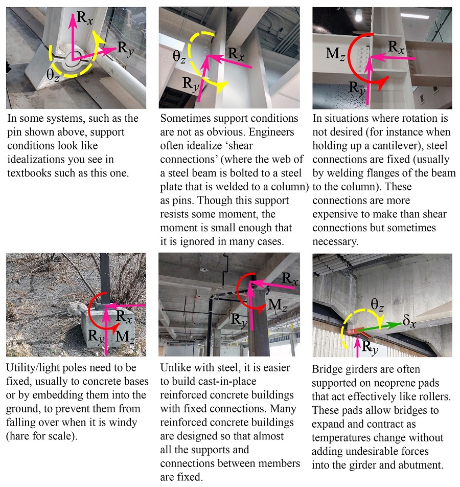
 = reaction force along x-axis,
  = reaction force along y-axis,
  = moment about z-axis,
  = permitted rotation about z-axis,
  = translation (permitted deformation) along x-axis. (Photos by D. Tomlinson)
Engineers select support types as part of the design process based on various factors including:
- The member’s expected use (e.g. a door fixed to its frame would no longer be a door).
- The member’s material and cost (e.g. welding steel to make a fixed connection is usually more expensive than bolting steel to make a pinned connection).
- Stability (i.e. members that do not have enough supports will move undesirably under small forces).
- Controlling the distribution of internal forces (e.g. tension, bending moments) in members. Internal forces are discussed in more detail in Chapter 7 of this book.
In this chapter we will ignore friction. Situations where friction cannot be ignored are discussed more in Chapter 8 of this book.
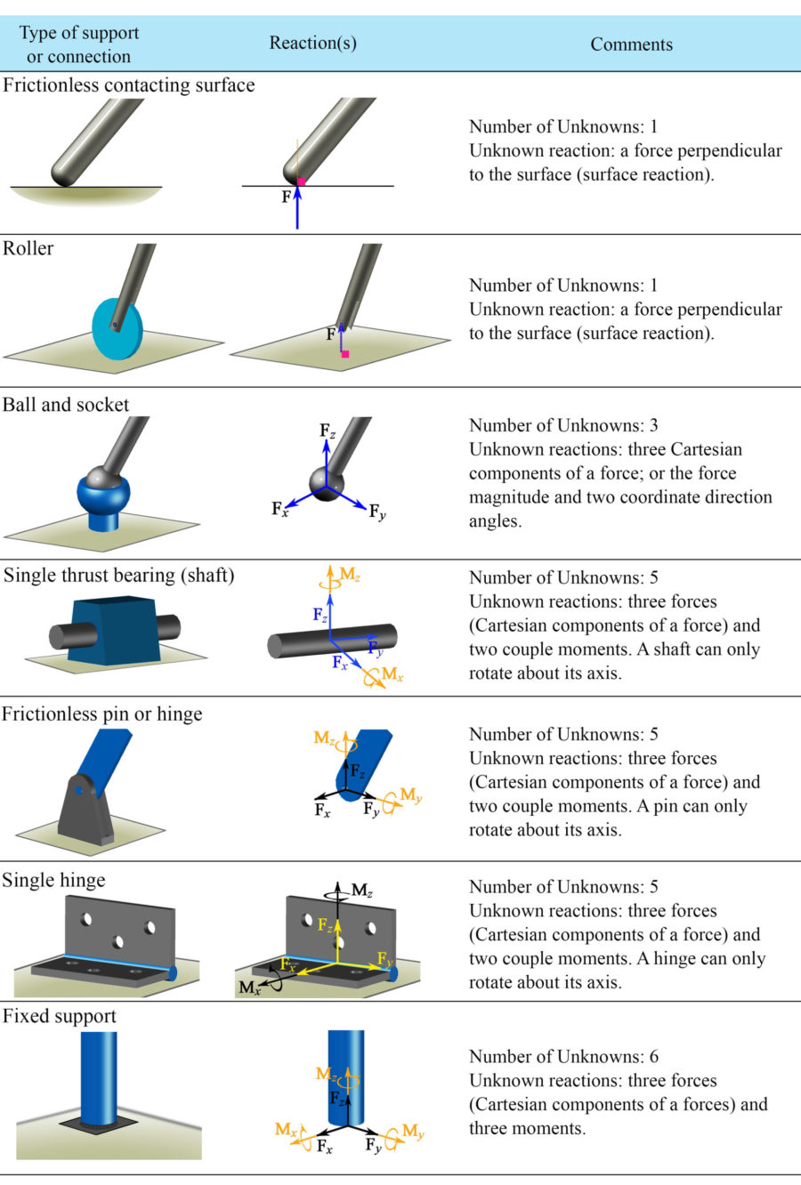
Spatial force systems (three dimensions)
In three dimensions, a point of a body can independently translate in three directions and the body can rotate about three independent axes. A support or connection can affect any of these translations or rotations by exerting opposing forces against the translations or rotations. Different three dimensional supports or connections are demonstrated in Table 4.2.
Steps for creating a free-body diagram
Four steps should be taken for constructing a FBD of a body:
1- Selecting the free body. The purpose of a FBD is for the analysis of the forces acting on it. We need to identify the forces we would like to calculate and select a free body that is carrying that force. If we need to analyze more than one forces or couple moments, we may need more than one FBD. The body we select should contain known magnitudes and/or directions that allow us to equate the unknown forces.
2- Constructing a free body. Isolate or cut (imaginarily) the body (or part of a body) from its surroundings by removing its supports or connections with adjacent bodies.
3- Recognizing and labeling the forces and couple moments. Show all forces and couple moments including the loads (active forces), unknown support and connection reactions (reactive forces), and internal forces and couple moments externally exposed after cutting the body on the free body. Then, label each force properly.
4- Expressing the forces by their components in the CVN or use the scalar formulation. Find the components of the loads and the unknown forces (support reactions and externally exposed internal forces); CVN or the scalar formulation can be utilized. This step, will simplify calculations in most of the problems.
The direct application of a FBD is to solve the equations of equilibrium toward finding the unknown support reactions and internal forces of a body. Next chapters are founded on the concept of FBDs and they present equilibrium equations and structural analysis.
Videos
Free-Body Diagrams:
Solving Support Conditions: