
Forces and Moments: Moments
Introducing a New Notation
Henceforth, we will use a new notation for simplicity. Recall that when a vector  is represented in CVN as
  , the capital letters
 ,
,  and
and  represent scalar components. Their values can be negative or positive, depending on the directions of the components relative to
  ,
,  , and
, and  . For simplicity and brevity in notations and formulations we introduce a magnitude-based notation and a scalar formulation starting in this section.
In the magnitude-based notation, the capital letters, such as  , , , and , represent the magnitudes of the vectors, i.e. ,
  ,
,  and
and  . This means they are positive.
Note that capital letters or bold letters are used to label the vectors. They are just for naming purposes. The direction is always indicated by the arrows.
When using the magnitude-based notation, the direction of a vector (specifically a vector component) referred to by a non-bold capital letter within the text is denoted by little arrows if needed. The following example clarifies this convention.
EXAMPLE
Consider the vector and its vector components and shown below.
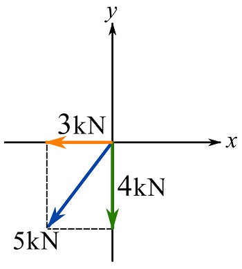
We can write,
![\[\begin{split}F_x &= 3 \text { kN}\leftarrow\\F_y &= 4 \text { kN}\rightarrow\\F &= 5 \text { kN}\swarrow\end{split}\]](https://engcourses-uofa.ca/wp-content/ql-cache/quicklatex.com-468d3cb15ef4b32f4f7da52ad5394afb_l3.png "Rendered by QuickLaTeX.com")
In the scalar formulation, the signs  or
or  in front of the (positive) variables, such as , , and , indicate the direction of the vectors with respect to predefined Cartesian axes x, y, and z.
For instance, in the case of coplanar forces  ,
,  , and
, and  in a Cartesian coordinate system, the resultant force
  is,
is,
![\[\bold R = \sum_i^n \bold F_i \]](https://engcourses-uofa.ca/wp-content/ql-cache/quicklatex.com-c83cc3b2f89ed063a43ccfc81eead50d_l3.png "Rendered by QuickLaTeX.com")
Decomposing the sum along the x and y axes as,
![\[\begin{split}\bold R_x &= \sum_i^n \bold F_{xi}\\\bold R_y &= \sum_i^n \bold F_{yi}\\\end{split}\]](https://engcourses-uofa.ca/wp-content/ql-cache/quicklatex.com-1babd96b01d4ae489b1c3449838aa453_l3.png "Rendered by QuickLaTeX.com")
we can use the scalar formulation to write,
![\[\begin{split}R_x &= \overset{+}{\rightarrow}\sum F_{ix}\\R_y &= +\uparrow\sum F_{iy}\end{split}\]](https://engcourses-uofa.ca/wp-content/ql-cache/quicklatex.com-cc84bb75486f1d71575cb5c07dddffc7_l3.png "Rendered by QuickLaTeX.com")
where the non-bold capital letters are magnitudes and the arrows ( ,
,  ) specify the positive directions of the Cartesian axes. If any of the vector components
  and
and  points in the negative direction of its corresponding axes, then a minus sign “” is added in front of its magnitude. This use of notation is clarified by an example as follows.
EXAMPLE
Considering the coplanar forces shown in the figure, formulate the resultant force in its Cartesian components.
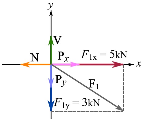
![\[\begin{split}\bold R_x = \sum \bold F_x \implies R_x &=\overset{+}{\rightarrow}\sum F_x= -N+P_x + 5 \text{ kN}\\\bold R_y = \sum \bold F_y \implies R_y &= +\uparrow\sum F_y = V - P_y - 3\text{ kN}\end{split}\]](https://engcourses-uofa.ca/wp-content/ql-cache/quicklatex.com-0156cb4a1d5ddb64faf1831ecde045ba_l3.png "Rendered by QuickLaTeX.com")
The minus sign in front of the magnitude of any of  ,
,  and
and  is because the vector is in the negative direction of its corresponding Cartesian axis.
Moment by a force
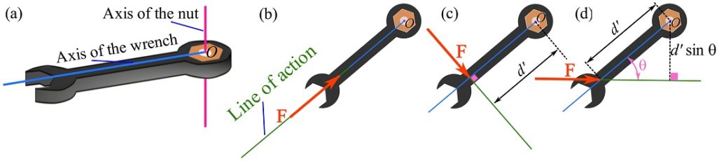
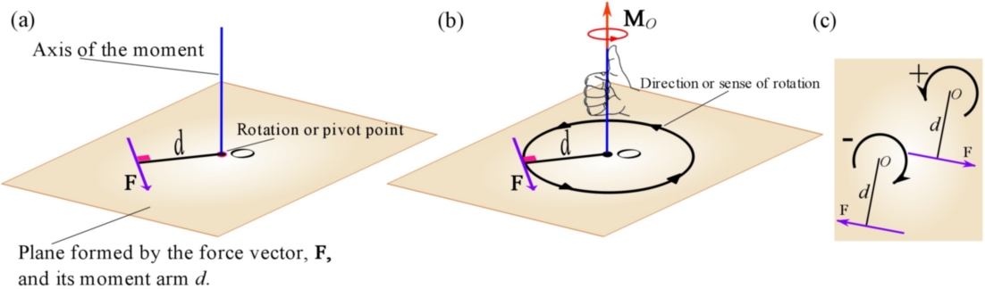
When a body is subjected to a force, the force may rotate or produce a tendency of rotation for the body. For a tangible example, consider a wrench applied to a nut or head of a bolt as shown in Fig. 3.8a. If we apply a force by pulling or pushing along the handle of the wrench, the wrench will not turn (Fig. 3.8b). However, the wrench and the nut will rotate or pivot about the vertical axis passing through the center of the nut (point  ) if we exert a force on either side of the handle (Fig. 3.8c). This tendency, created by a force, to rotate, twist, or pivot a body, is called a torque or the moment caused by a force; or simply the moment.
We should pay attention to the term tendency. In the wrench example, we are able to keep turning and fastening the nut to a certain degree beyond which we are not able to turn the wrench anymore (due to muscle weakness for instance). However, we are still able to push or pull the wrench and generate a tendency of rotation on the nut.
We can experiment to find that the extent of rotation of the wrench depends on how hard we exert the force on the handle. Also, we can change the position of our hand on the handle of the wrench; the further our hand is away from the nut, it gets easier (less force is needed) for turning or fastening the nut. Moreover, we can understand that changing the angle of the force applied on the handle makes it easier or harder to rotate the wrench or the nut; the easiest effort comes when our hand is perpendicular to the handle (Fig. 3.8c and d). These observations indicate that the magnitude of the moment (tendency of rotation) depends on the angle between the line of action of the force and the handle, the magnitude of the force, and the distance between the pivoting point and the point at which the force is applied.
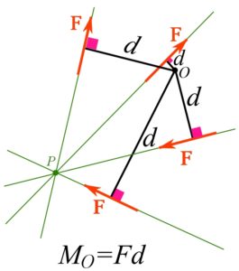
The magnitude of a moment of a force about a point (pivot point), , caused by a force, can be calculated with the following scalar formula.
(3.12) ![\[M_O= F d\]](https://engcourses-uofa.ca/wp-content/ql-cache/quicklatex.com-3ba769ee62a8a8309a7286b54ea577e8_l3.png "Rendered by QuickLaTeX.com")
where is the magnitude of the force (absolute value) and  is the perpendicular distance (absolute value) from the pivot point to the line of action of the force as demonstrated in Fig 3.9.
Equation 3.12 indicates that the magnitude of a moment only depends on the magnitude of the force, , and the perpendicular distance from the pivot point, to the line of action of the force. This perpendicular line segment is called the moment arm. By Eq. 3.12, the dimension and unit of the moment are  and
and  respectively.
In the example of a wrench, Fig. 3.8, the magnitude of the moment is  .
.
Remark: the line of action of a force, and the moment arm are coplanar.
Remark: the moment of a force about a point on the line of action of the force is zero (because  ). It is intuitive as well.
Remark: a moment is not a rotation, but, it causes rotation or a tendency to rotate.
The following interactive tool illustrates how the moment of a force (blue vector) about the point is calculated. The force is acting at the point  .
.
Direction of a moment
Since the rotation tendency has a direction and the tendency is caused by a moment, , a moment has a sense of direction. The direction of a moment is defined and expressed by its moment axis and the right-hand rule. The axis of a moment is a line passing through the pivot point and perpendicular to the plane that contains the force vector (line of action of the force) and its moment arm (Fig. 3.10a). The right-hand rule is then utilized to establish the direction of the moment. By this rule, when fingers curl in the rotation direction, the thumb indicates the sense of an arrow defining the moment direction on the moment axis (3.10b).
Having both a magnitude and a direction, a moment is in fact a vector quantity. For two-dimensional (or coplanar) problems, where all forces (and pivot points) lie in a plane (say x-y plane), all moment vectors are perpendicular to the plane (and along the z axis). To make a moment vector easily seen, it is shown by a curled arrow. By convention, a counterclockwise rotation is associated with a positive moment, and a clockwise rotation with a negative moment (3.10c). This sign convention is not mandatory and either direction can be set as the positive direction. However, it is important that the positive direction selected is consistent through solving a problem.
Principle of Transmissibility
The location of the point at which the force is acting does not affect its moment about a given point as long as the point is selected on the line of action of the force (Fig 3.11). This fact is referred to as the principle of transmissibility stating that sliding a force along its line of action does not change its moment about a given point. By this principle, a force vector is designated as a sliding vector. The proof of this principle using vector calculation is presented in the next subsection.
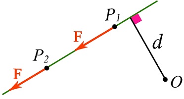
Remark: the moment of a force about a point does not depend on the point (on the body) at which the force is acting as long as the force slides (changes position) along its line of action.
Principle of moments (Varignon’s Theorem)
The principle of moments or Varignon’s theorem (Pierre Varignon (1654–1722) states that the moment of a force about a point equals the sum of the moments of the components of the force about the point. For a two-dimensional example, a force  where
where  and
and  are coplanar components of as shown in Fig 3.12a. Then, the principle of moments declares that,
![\[\circlearrowleft{+} M_O=-Fd=-F_1d_1 + F_2d_2\]](https://engcourses-uofa.ca/wp-content/ql-cache/quicklatex.com-6993aded220c14529fae555e6c33e1ee_l3.png "Rendered by QuickLaTeX.com")
where ,  and
and  are the magnitudes of , and ; and ,
  , and
, and  are the moments arms of , and respectively. Note that the counterclockwise rotation is associated with positive moments (Fig 3.10c), therefore the moment of and about are negative and the moment of about is positive.
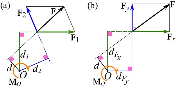
Calculating the moment of a force about a point usually becomes simpler when using the Cartesian components of the force and with principle of moments. For example, the following equation holds for the force and its Cartesian components shown in Fig. 3.12b.
![\[\circlearrowleft{+} M_O=-Fd=-F_xd_{F_x} + F_yd_{F_y}\]](https://engcourses-uofa.ca/wp-content/ql-cache/quicklatex.com-bf9f8b966a0ec3e5953028283bd7006a_l3.png "Rendered by QuickLaTeX.com")
where , and are the magnitudes of , and respectively.
Remark: for calculating the moment of a forces about a point in two-dimensions, the magnitudes of the rectangular components of the force are used. In other words, the absolute values of the scalar components are involved.
The following interactive tool illustrates the principle of moments for calculating the moment of a force about a point in two-dimensions. Change the direction of the force and observe how its moment about the point is calculated based on the moments of the force components.
The vector form of the principle of the moments is presented in the next section.
EXAMPLE 3.2.1
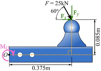
Determine the moment of the force, acting on the trailer ball mount, about point shown in the figure. Use the principle of the moments.
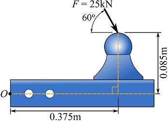
SOLUTION
Determine the rectangular components of the force (see figure below).
![\[\begin{split}\bold F&= \bold F_x + \bold F_y\\F_x &= 25\cos 60^\circ =12.5\text{ kN}\rightarrow \\F_y &= 25\sin 60^\circ = 21.7\text{ kN} \downarrow\end{split}\]](https://engcourses-uofa.ca/wp-content/ql-cache/quicklatex.com-c815f47d04e3f2924922602c732cbc01_l3.png "Rendered by QuickLaTeX.com")
Determine the moment of each of the force components about point and scalar-add the together. The counterclockwise rotation is associated with positive moments.
![\[\begin{split}M_O=-(F_x)(0.085)-(F_y)(0.375)&=-(12.5)(0.085)-(21.7)(0.375)= -9.2\text{ kN.m}\\\implies \quad M_O&=9.2\text{ kN.m}\circlearrowright\end{split}\]](https://engcourses-uofa.ca/wp-content/ql-cache/quicklatex.com-8711f297a627df0ce9b52e3c6d89a7d6_l3.png "Rendered by QuickLaTeX.com")
Cross product for moment calculation
The formulation of moment magnitude,  , is called the scalar formulation. Although this formulation gives the moment magnitude, it does not provide the direction of the moment. To express a moment in its vector form, including both magnitude and direction, the vector cross product (Section 2.8) is recruited. The moment (vector) of a force about point is,
(3.13) ![\[\bold M_O=\bold r \times \bold F\]](https://engcourses-uofa.ca/wp-content/ql-cache/quicklatex.com-e38d7796b461b682d2b82a184f495fc8_l3.png "Rendered by QuickLaTeX.com")
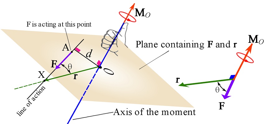
where  is a position vector directed from the pivot point O to any point (X) on the line of action of the force vector (Fig 3.13). The vector is not necessarily the moment arm, but it can be called the quasi-moment arm vector or moment arm vector. This formulation of the moment of a force is referred to as the vector formulation. he nature of the cross product provides both magnitude and direction for a moment. The magnitude of a moment is the magnitude of its cross product formulation,
(3.14) ![\[M_O=|\bold M_O|=\vert \bold r\times\bold F \vert = rF\sin \theta=F(r\sin \theta)=Fd\]](https://engcourses-uofa.ca/wp-content/ql-cache/quicklatex.com-8d5745b282f40a1b419b026e394644d4_l3.png "Rendered by QuickLaTeX.com")
which agrees with Eq. 3.12.
The direction of  , indicated by the cross product, is perpendicular to both and . In other words, is perpendicular to the plane containing and (it is equivalent to say that the plane contains and the line of action of the force). The vector formulation of a moment is demonstrated in Fig 3.13.
Remark: the order of the operation resulting in matters; by the properties of the cross product  . Only
  will give a direction that complies with the direction indicated by the right-hand rule mentioned earlier.
The CVN facilitates calculating moments expressed by the vector formulation. With and expressed in CVN, the moment of about a point becomes,
(3.15) ![\[\begin{split}\bold M_O&=\bold r \times \bold F=(r_x\bold i+r_y\bold j+r_z\bold k)\times(F_x\bold i+F_y\bold j+F_z\bold k)\\&= (r_yF_z-r_zF_y)\bold i-(r_xF_z-r_zF_x)\bold j+(r_xF_y-r_yF_x)\bold k\end{split}\]](https://engcourses-uofa.ca/wp-content/ql-cache/quicklatex.com-54f5e566fc6462119056bcb4ef9e585d_l3.png "Rendered by QuickLaTeX.com")
which can be evaluated through the symbolic use of the determinant (see Section 2.8) as,
(3.16) ![\[\bold M_O=\bold r \times \bold F=\left\|\begin{matrix}\bold i & \bold j & \bold k \\r_x & r_y & r_z \\F_x & F_y & F_z \\\end{matrix}\right\|\]](https://engcourses-uofa.ca/wp-content/ql-cache/quicklatex.com-757e11a8010e6a5df39cdff0e9038268_l3.png "Rendered by QuickLaTeX.com")
where the determinant evaluated as (see Section 2.8),
![\[\left\|\begin{matrix} \bold i & \bold j & \bold k \\ r_x & r_y & r_z \\ F_x & F_y & F_z \end{matrix}\right\|=\left\|\begin{matrix} r_y & r_z \\ F_y & F_z \end{matrix}\right\|\bold i - \left\|\begin{matrix} r_x & r_z \\ F_x & F_z \end{matrix}\right\|\bold j + \left\|\begin{matrix} r_x & r_y \\ F_x & F_y \end{matrix}\right\|\bold k\]](https://engcourses-uofa.ca/wp-content/ql-cache/quicklatex.com-9b2c1b58029dff5d3048215fca933b3b_l3.png "Rendered by QuickLaTeX.com")
The following interactive example demonstrates the vector formulation of the moment of a force about a point in three dimensions.
Proof of the Principle of Transmissibility (Vector Form)
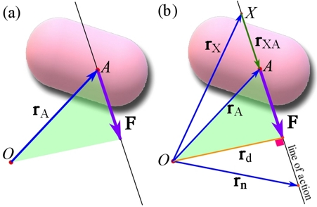
Suppose a body and a force acting at a point  of the body (Fig. 3.14a). Consider a point anywhere in the space (may also be a point of the body) but not on the line of action of . If the moment arm vector
  is considered, the moment of about is
  . Similarly, the moment of about point is
  if any other point
  on the line of action is chosen to construct a moment arm vector as
  . Our purpose is now to prove
  . The key to this proof is noting that there exist a position (displacement) vector
  on the line of action such that
  (Fig. 3.14b). Thereby,
![\[\bold M^A_O=\bold r_A\times \bold F=(\bold r_X + \bold r_{XA})\times \bold F=(\bold r_X\times \bold F)+ (\bold r_{XA}\times \bold F)=(\bold r_X\times \bold F)+ (\bold 0)=\bold M^X_O\]](https://engcourses-uofa.ca/wp-content/ql-cache/quicklatex.com-5a8ee594a71f8a296d1c74ebc42b1b1a_l3.png "Rendered by QuickLaTeX.com")
proves the principle. The proof uses the distributivity of the cross product. The term  is zero because the vectors are collinear, or the angle between them is zero. Since the above proof holds for any two moment arm vectors (Figure 3.14b shows some possibilities), the moment is independent of the location of being on the line of action.
The Principle of moments (Varignon’s Theorem) for a vector in CVN
Let  be a force with , and as its Cartesian components. Then, the following equation holds for the moment of and its components about a point .
(3.17) ![\[\bold M_O=\bold r \times \bold F=\bold r \times (\bold F_x+\bold F_y+\bold F_z)= \bold r \times \bold F_x+\bold r \times \bold F_y+\bold r \times \bold F_z\]](https://engcourses-uofa.ca/wp-content/ql-cache/quicklatex.com-c9a13a0a7672abbdc57dfe453ec68991_l3.png "Rendered by QuickLaTeX.com")
In the previous subsection, the moment of a force about a point has been discussed. A key concept regarding a moment is that a moment is created about a point and has an axis passing through the point. Physically, the tendency of rotation created at the point by the moment is about an axis perpendicular to the plane of the force and the point(Fig. 3.10 and 3.13). In reality, an object may be only allowed to rotate around a specific axis, which could be not perpendicular to the plane. On the other hand, a moment is a vector quantity and consequently it can have components along different axes as well. Therefore, a quantity can be found as the moment about an axis.
For example, applying a vertical force on the handle of an L-shape wrench to loosen a lug nut of a car tire creates a moment () at the nut () with the axis of the moment as shown in Fig. 3.15. The axis of the moment is neither along the handle nor along the extension bar of the wrench. If we are interested to find the moment (as a component of ) that rotates the nut, we should find the moment ( ) whose axis is along the wrench extension bar being the y axis in the figure.
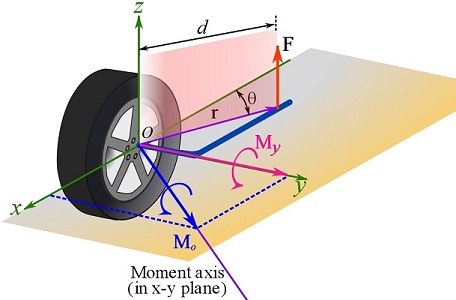
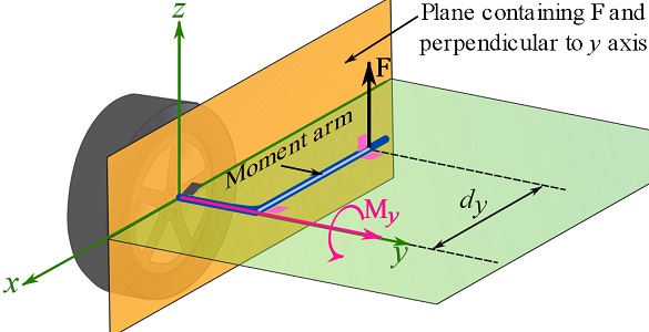
In the particular case shown in Fig. 3.16, where (the line of action of) is in a plane perpendicular to the specified axis of interest (the y axis), the magnitude of the moment of about the y axis is  where
where  is the moment arm of in the plane perpendicular to the moment axis (Fig. 3.16).
In two dimensional problems where all forces are coplanar in a plane, say  plane (e.g. Fig 3.10), any moment about any point in the plane is in fact a moment about the z axis (or an axis parallel to the z axis).
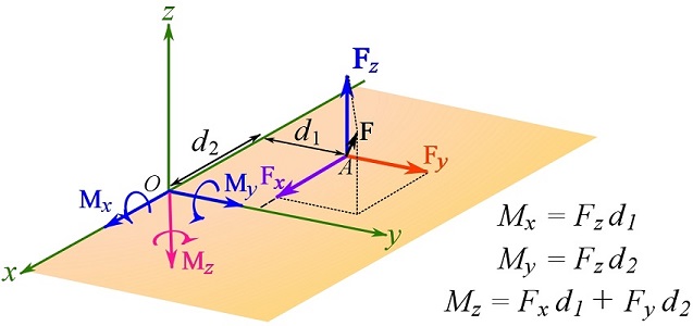
Another case is obtaining the moments of a force (at some point of the space) about the three Cartesian axes. This problem simplifies if the application of the force is slid to the x-y plane (or the x-z or y-z plane) and then resolve the force into its rectangular components. An example is shown in Fig. 3.17. A force is at point in the x-y plane (or in some plane parallel to x-y plane). Each component creates some moment(s) about some Cartesian axis (or axes) as shown in the figure.
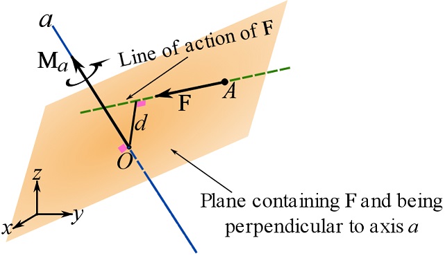
In general, determining the magnitude of the moment of a force about an specified axis needs finding a plane containing the line of action of the force and perpendicular to the axis of interest, and then finding the moment arm of the force in the plane (Fig 3.18). This approach is called the scalar formulations.
Calculations using the scalar formulation of the moment of a force about an axis is not always easy in three dimensions. Therefore, a vector formulation is used.
Let be a force and an arbitrary point of a specified axis  as demonstrated in Fig. 3.19. Then the moment of the force about is
  , where, is the quasi-moment arm vector constructed from to any point of the line of action of the force (Fig. 3.19).
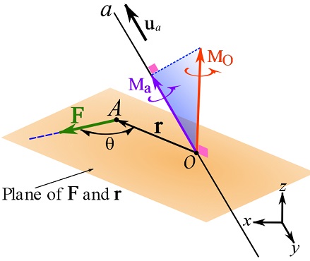
If  is the unit vector of axis , then the component of along the specified axis is determined by the dot product,
(3.18) ![\[\begin{split}\bold M_a&=M_a \bold u_a\\M_a=\bold u_a \cdot\bold M_O&=\bold u_a\cdot(\bold r\times \bold F)\end{split}\]](https://engcourses-uofa.ca/wp-content/ql-cache/quicklatex.com-32884071cf796260dbbc302dcd63c8fa_l3.png "Rendered by QuickLaTeX.com")
The term  is called the triple scalar product. The triple scalar product orthogonally projects the vector onto an axis with the direction defined by . The quantity
  is a scalar; a positive value indicates that
  is in the direction of , whereas a negative value indicates that is in the opposite direction of the axis. See Section 2.7 for more information.
If  and are expressed using CVN, their scalar components can form a matrix as,
![\[\begin{bmatrix}u_{a_x} & u_{a_y} & u_{a_z}\\r_x & r_y & r_z\\F_x & F_y & F_z\end{bmatrix}\]](https://engcourses-uofa.ca/wp-content/ql-cache/quicklatex.com-999535c794443cb3763eb2398d301605_l3.png "Rendered by QuickLaTeX.com")
and the triple scalar product can be computed by calculating the determinant of the matrix,
(3.19) ![\[M_a=\bold u_a\cdot(\bold r\times \bold F)= \left\|\begin{matrix}u_{a_x} & u_{a_y} & u_{a_z}\\r_x & r_y & r_z\\F_x & F_y & F_z\end{matrix}\right\|\]](https://engcourses-uofa.ca/wp-content/ql-cache/quicklatex.com-4cdac7fee8d605cb64c6f6d9ac9a7595_l3.png "Rendered by QuickLaTeX.com")
The proof is by expanding the equation and comparing it with the determinant result.
Remark: for determining the moment of a force about a specified axis, both the location and the direction of the axis influence the results.
Remark: the physical meaning of the Cartesian components of a moment vector are moments about the three Cartesian axes.
In the following interactive example, we intend to determine the moment of a force, applied at a corner of the pyramid, about either of the specified axes  or
or  . In the example,
  is the moment of about point
  ,
,  is the moment of about the axis , and is the moment of about the axis .
Videos
Calculating Moments in 2D:
Calculating Moments in 3D (About a Point or Axes):