
Internal Forces: Types of internal forces
The internal forces between the particles (molecules/atoms) of a body maintain the integrity of the body. The internal forces inside a body are directly affected by the (external) loads acting on a body. Therefore, designing a body to properly resist the external loads and maintain its integrity requires complete knowledge of the internal forces within the body.
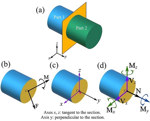
The internal forces in a body can be investigated or determined by (imaginarily) plane-sectioning or slicing the FBD of the body. Slicing or sectioning a body externally exposes the internal forces on the cross section. The exposed internal forces, being in fact a continuous distribution of forces over the cross section, can be presented by resultant forces and couple moments on the imaginary boundary or cross section (Chapter 4).
The resultant forces and a couple moment (Fig 7.1a)are usually shown three orthogonal axes (i.e. a Cartesian frame) with one of them perpendicular to the cross sectional plane as shown in Fig 7.1b. The components of the internal forces and the couple moment along these axes are shown in Fig 7.1c. These components are classified and explained as the following.
1- Normal force. Denoted by  , the normal force is the internal force component that is perpendicular to the cross section (Fig 7.1d).
2- Shear force. The shear force is the internal force component that is tangent to the cross section. The shear force can have two rectangular components  and
and  as shown in Fig 7.1d.
3- Bending moment. The bending moment is the internal couple moment (vector) that is tangent to the cross section. The bending moment can have two components  and
and  as shown in Fig 7.1d.
4- Torsional moment. The torsional or twisting moment is the internal moment component that is perpendicular to the cross section. The moment component  in Fig 7.1d is a torsional moment.
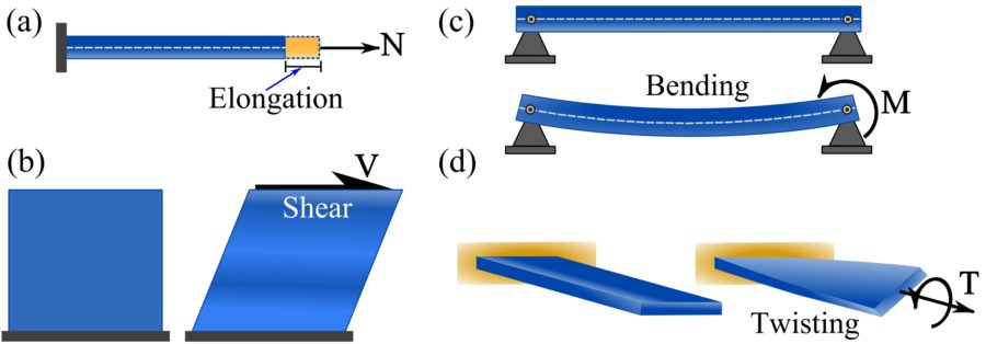
The classification of the internal forces and couple moments is based on the deformations (physical effects) they cause on a body. To have an understanding of the deformations that the internal forces and couple moments produce, consider the following example.
1- The deformation caused by a normal force is elongation or compression of a body. This can be observed by applying a pulling or pushing force at the tip and along the axis of a bar as shown in Fig. 7.2a.
2-The deformation caused by a shear force is shearing or sliding of layers of a body relative to each other. This can be observed by applying a force tangent to a surface of a block (e.g. a match box) as shown in Fig. 7.2b. Note how the top of the block is shifted in one direction.
3- A bending moment bends the body in the plane of the moment. This deformation can be experienced by rotating a tip of a bar without translating the tip in any direction as shown in Fig. 7.2c.
4- A torsional moment rotates the sections of a body about an axis perpendicular to the sections. The deformation created by a twisting moment on a bar is shown in Fig. 7.2d. A tangible example is twisting a towel.
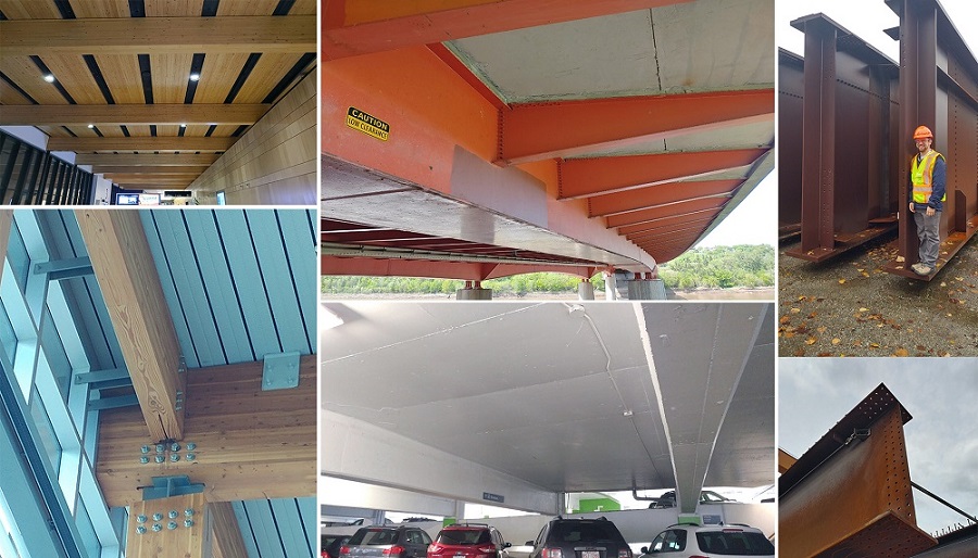
In this course, we focus on the internal forces and couple moment of two dimensional beams. A beam is a long structural member having its dominant loading perpendicular to the long axis of the member. Some instances of beams are shown in Fig. 7.3.
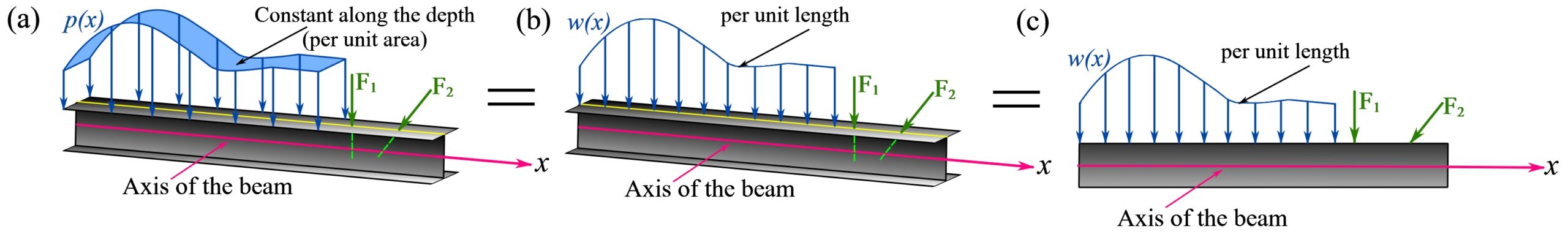
A two-dimensional beam is a beam that its external and internal forces (or their resultants) can be idealized to be coplanar with the axis of the beam. Also, the external and internal couple moments are perpendicular to the plane of forces. In this case, the distributed loads (per unit area) are simplified to distributed loads along the axis (per unit length) of the beam (see Section 3.5). For example, Fig. 7.4 shows conditions under which a beam is considered as a two-dimensional beam.
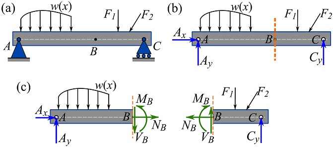
The internal forces of a (loaded) beam can be exposed by the method of section. Consider a beam shown in Fig. 7.5a. To reveal the internal forces and couple moment at point  , the FBD of the beam is drawn (Fig 7.5b) and an imaginary section perpendicular to the axis of the beam through is made (Fig 7.5b). Sectioning the beam results in two segments. The (resultant) internal forces and moments at the imaginary section in each FBD are demonstrated in Fig. 7.5c. Note that, the exposed internal forces and moment appear in the form of action-and-reaction pairs on each side of the cross section.
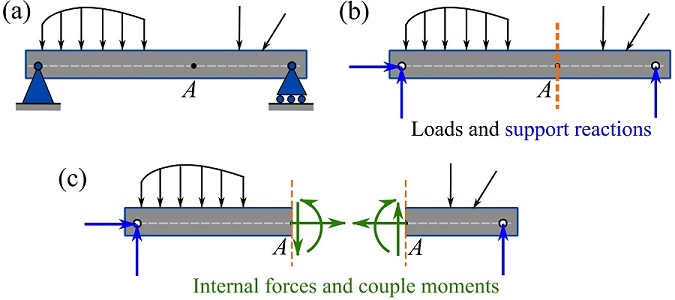
Remark: The cross section of a beam is perpendicular to the axis of the beam (in this course).
The Internal forces and couple moment (Fig 7.5c) in a (two-dimensional) beam are classified into three types:
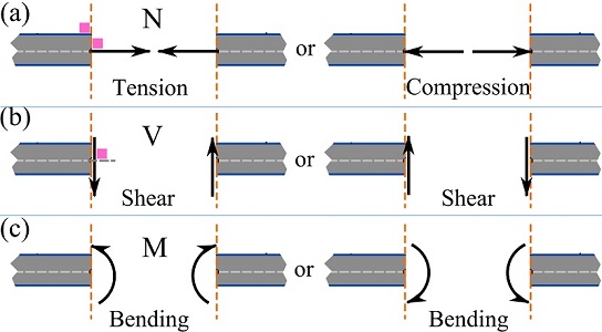
1- Axial force or normal force (N). The normal force is directed along the axis of a beam and perpendicular to a cross section of the beam. The normal force at a point is either tensile or compressive (Fig7.6a).
2- Shear force (V). A shear force is perpendicular to the beam axis or tangent to the plane of the cross section. When we deal with horizontal beams with vertical cuts, the shear forces will be directed “up” and “down” (Fig 7.6b).
3- Bending moment (M). A bending moment is a couple moment causing a beam to bend and deflect in a plane, i.e. in two dimensions (Fig 7.6c).
Sign Convention for Internal Forces
A sign convention augmented to a force is to express the physical nature or type of the force. Take the member forces in trusses as an example, tensile or stretching member force is positive and compression is negative. It is important to distinguish between the sign of a force assigned to specify the type of the force and the sign convention of a force (component) based on the force’s direction . In summary, there are two sign conversions for a force:
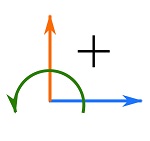
1- The point sign convention. A sign convention set for writing the equilibrium equations. This sign convention is based on the coordinate system utilized and assigns positive and negative signs to the components of the forces involved in the equations of equilibrium. The point sign convention used in this book is shown in Fig. 7.7
The member (beam) sign convention. A sign convention set to assign signs to the (internal) forces of a member according to their physical effects, similar to that member forces of trusses.
For a beam, the internal forces and couple moment follow these sign conventions:
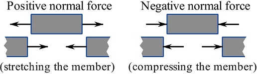
1- A normal force is said to be positive if it is a tension force i.e. a force tending to stretch the member. A compressive force is then a negative force. Figure 7.8 shows positive and negative normal forces acting on a free beam segments.
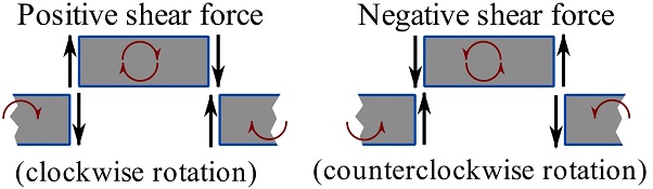
2- A shear force is said to be positive if it creates a clockwise rotation of the segment it acts on. A shear force is then negative if it tends to rotate a segment counterclockwise. Figure 7.9 shows positive and negative shear forces acting on free beam segments and sections.
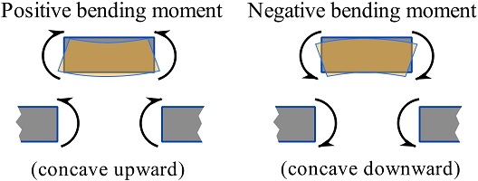
3- A bending moment on a segment is said to be positive if it tends to bend the segment concave up. A negative bending moment bends the segment concave down. Figure 7.10 shows positive and negative bending moments acting on free beam segments and sections.
Context: Internal Forces
- So far, we have assumed that loads transfer to supports but have ignored asking “how?” Exception: the method of joints and method of sections allowed us to find normal (aka axial) forces in trusses.
- For engineers to design a structure, they need to consider how force transfers from one location (e.g. from where the force is applied) to another (e.g. the ground). For instance, if you are reading this inside a building right now, your weight needs to make it to the earth through the building’s slabs, beams, walls, and/or columns.
- Internal forces transfer through members between external loads and supports (i.e. these are forces that the member ‘feels’).
- Internal forces are the most important factor that engineers need to consider when completing the structural design of load carrying members. The magnitude and sense of internal forces affect member shape, material, and dimensions.
Applications: Why are internal forces important?
Looking around, you can find evidence of how internal forces influence structural design. Bridge girders are often well over a metre deep since they need to support heavy loads over a long span while floor joists in a house are typically ~150 mm deep since they carry light loads over a short span.
Bending moments cause tension on one side of a beam and compression on the other side (recall force couples in Section 3.3 of this book). Concrete is strong in compression but weak in tension. To make up for this weakness, concrete is often reinforced (usually with steel reinforcing bars aka ‘rebar’) with materials strong in tension. Engineers specify rebar in areas that expected to carry tension under design loads. The larger the expected tension forces, the more rebar needed to resist those forces.
Nothing is invincible. If internal forces become too large the member will fail. Structural engineering researchers use destructive tests to compare the real response of structures to computer simulations and simplified design equations to optimize engineering practice and make our structures safer and more efficient. The concrete beam in Fig. 7.11a failed because the bending moment induced by a large hydraulic press caused concrete to crush on the top of the beam. Reinforcement concentrated in the bottom of the beam (Fig. 7.11b) prevented the beam from snapping in half under very little force (which would have happened if the reinforcement was not there). Though the beam failed, it was able to carry loads well above those it would have been designed for in the real world.
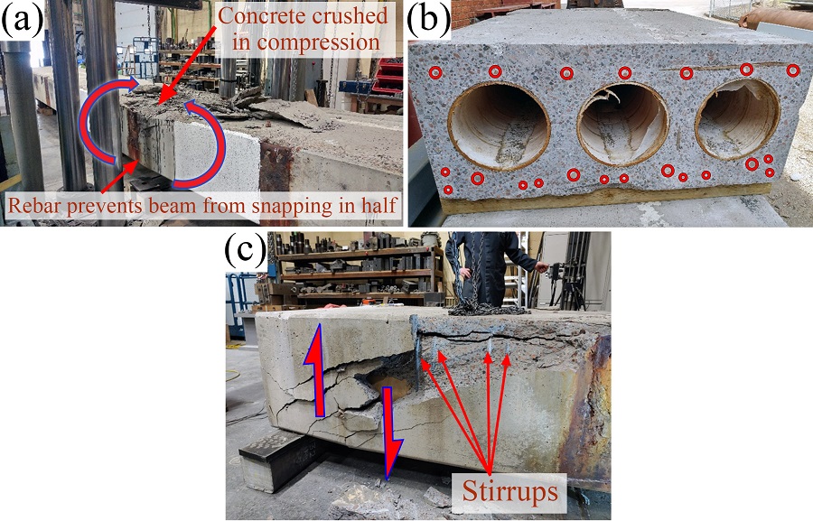
If forces are applied near the end of a beam, shear forces will be high while bending moments will be low (discussed in Section 7.2 of this book). Shear failures in concrete can be sudden and disastrous. For instance, the failure of the De La Concorde overpass near Montreal in 2006 prompted significant investigations into the design and maintenance of Canadian bridges. To resist shear, concrete beams are often reinforced with vertical rebar (called ‘stirrups’) that prevents beams from splitting apart under load (Fig. 7.11c). Stirrups are concentrated in areas where shear forces are expected to be large. Shear failure in concrete is easily recognized by the presence of diagonal cracks (rather than vertical or horizontal cracks seen in other cases). The reason why shear cracks are diagonal is explained in future courses.
Analysis Procedure of internal forces
The internal forces can be determined by the method of section (cut the member to expose the internal forces). For two-dimensional beams, this is a two-dimensional rigid body equilibrium problem satisfying the three equilibrium equations (see Section 5.2),
![\[\begin{split}\sum F_x &= 0\\\sum F_y &= 0 \\\sum M_O&=0\end{split}\]](https://engcourses-uofa.ca/wp-content/ql-cache/quicklatex.com-ed28d549bb98cdf45ec5520c25280ecc_l3.png "Rendered by QuickLaTeX.com")
Implementing the method of section for determining internal forces requires the following steps.
- Draw the FBD of the entire structure (beam) to obtain support reactions (not needed if the reactions are not involved in the equilibrium equations of a segment).
- Cut or section the free body into two sections at the location where the internal forces are required.
- Select one section, draw and label the exposed unknown internal forces (assume positive directions according to beam sign convention).
- Apply the equations of equilibrium (point sign convention).
- Solve for the internal forces.
Note that for labeling the forces and couple moments in two-dimensional problems, non-bold capital letters denote the magnitudes of the forces and couple moments. An example is shown in Fig 7.12.
EXAMPLE 7.1.1
Determine the internal forces and couple moment at point  of the beam shown in the figure. Follow the five steps of the method of section.
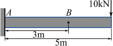
SOLUTION
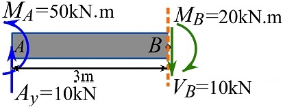
1- Draw the FBD of the beam to determine support reactions. Assume the unknown directions following the point sign convention (Fig 7.7).
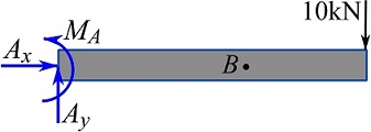
The support reactions are,
![\[\begin{split}\overset{+}{\rightarrow}\ \sum F_x&=0\implies A_x=0\text{ kN}\\+\uparrow\ \sum F_y&=0\implies A_y-10=0 \implies A_y=10 \text{ kN}\uparrow\\\circlearrowleft{+}\ \sum M_A&=0\implies M_A-(10)(5)=0\implies M_A=50\text{ kN.m}\circlearrowleft\end{split}\]](https://engcourses-uofa.ca/wp-content/ql-cache/quicklatex.com-7dda9f7880c86e649ff49a75fce239de_l3.png "Rendered by QuickLaTeX.com")
2- Cut or section the free body into two sections at the location where the internal forces are required.
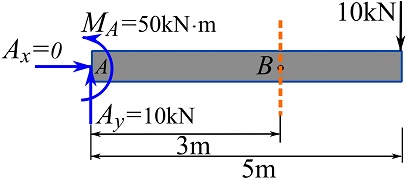
3- Select one section, draw and label the exposed unknown internal forces (assume positive directions according to beam sign convention).
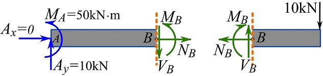
To show that selecting any of the segments (or the section on a segment) leads to the same internal forces and bending moment, we solve for the internal forces and moment on both segments.
Selecting the segment or section on the left-hand side
4- Apply the equations of equilibrium (point sign convention), and
5- Solve for the internal forces.
![\[\begin{split}\overset{+}{\rightarrow}\ \sum F_x&=0\implies N_B=0\text{ kN}\\+\uparrow\ \sum F_y&=0\implies 10-V_B=0 \implies V_B=10\text{ kN} \downarrow \\\circlearrowleft{+}\ \sum M_A&=0\implies 50-(V_B)(3)+M_B=0\implies 50-(10)(3)+M_B=0\\\implies M_B&=-20\text{ kN.m}\implies M_B=20\text{ kN.m} \circlearrowright\end{split}\]](https://engcourses-uofa.ca/wp-content/ql-cache/quicklatex.com-93c8ec0d49de71204736b00ca9644bfc_l3.png "Rendered by QuickLaTeX.com")
Therefore,  is a positive shear force and
  is a negative bending moment. The internal force and moment are shown as,
Selecting the segment or section on the right-hand side
4- Apply the equations of equilibrium (point sign convention), and
5- Solve for the internal forces.
![\[\begin{split}\overset{+}{\rightarrow}\ \sum F_x&=0\implies N_B=0\text{ kN}\\+\uparrow\ \sum F_y&=0\implies -10+V_B=0 \implies V_B=10\text{ kN} \uparrow \\\circlearrowleft{+}\ \sum M_B&=0\implies M_B-(10)(2)=0\\\implies M_B&=20\text{ kN.m}\circlearrowleft\end{split}\]](https://engcourses-uofa.ca/wp-content/ql-cache/quicklatex.com-c00154c01f3c18ceb4627509f077886b_l3.png "Rendered by QuickLaTeX.com")
Therefore, is a positive shear force and is a negative bending moment. The internal force and moment are shown as,
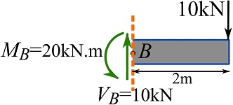
As it can be observed, choosing any of the segments (or sections) led to the same result. For this particular problem, selecting the right-hand segment for determining the internal forces and moment does not require solving for the support reactions beforehand.
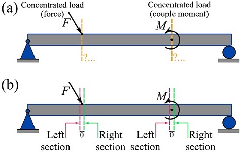
Sections near a concentrated load
One may wonder about finding the internal forces and couple moments of a beam exactly at a point where a concentrated load (force or couple moment) is applied (Fig. 7.13a). In reality, a concentrated load is still applied over an area (a length). Therefore, we don’t need to cut right at the point. However, a section can be made exactly on the right or left side of the location (point) of a concentrated load. As shown in Fig. 7.13b, sectioning exactly on the right or left side of a concentrated load clearly specifies the free segment that includes the concentrated load.
EXAMPLE 7.1.2
Considering the beam shown, determine the shear force and bending moment at .
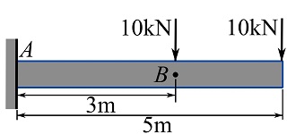
SOLUTION
Draw the FBD of the beam. Create sections on the left and right hand sides of point (the location of the concentrated load).
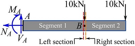
You can notice that the internal shear force and bending moment can be determined regardless of knowing the support reactions if you pick Segment 2. Considering the two sections on different sides of point , draw the FBDs of Segment 2 (shown below).
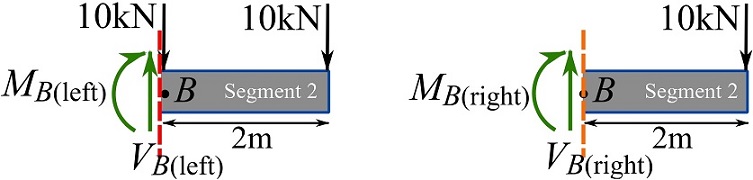
Write the equations of equilibrium for each case, and determine the internal shear forces and bending moments as,
![\[\begin{split}+\uparrow\ \sum F_y&=0\implies V_{B\text{(left)}}-10 -10=0 \implies V_{B\text{(left)}}=20\text{ kN} \uparrow \\\circlearrowleft{+}\ \sum M_{B\text{(left)}}&=0\implies -M_B-(10)(2)=0\implies M_{B\text{(left)}}=20\text{ kN.m}\circlearrowleft\end{split}\]](https://engcourses-uofa.ca/wp-content/ql-cache/quicklatex.com-bacec7dae112b1979fa18bb3a69fb454_l3.png "Rendered by QuickLaTeX.com")
and,
![\[\begin{split}+\uparrow\ \sum F_y&=0\implies V_{B\text{(right)}}-10=0 \implies V_{B\text{(right)}}=10\text{ kN} \uparrow \\\circlearrowleft{+}\ \sum M_{B\text{(right)}}&=0\implies -M_B-(10)(2)=0\implies M_{B\text{(right)}}=20\text{ kN.m}\circlearrowleft\end{split}\]](https://engcourses-uofa.ca/wp-content/ql-cache/quicklatex.com-f4224534eebe80c179f41cd85d0e4c97_l3.png "Rendered by QuickLaTeX.com")
As we can observe,  is not equal to
  . However,
  . This implies that a concentrated force creates a jump (up or down) in the value of
  . Similarly, a concentrated couple moment would create a jump in the values of
  .
.