Review of single and multi-degree of freedom (mdof) systems: Equivalent spring constants
One of the components we need in these equations of motion is the spring constant ![]() . We can often find this for a system using static techniques. This is easily generalized for MDOF systems.
. We can often find this for a system using static techniques. This is easily generalized for MDOF systems.
For SDOF systems, we can imagine the static response of the system using one of the approaches:
1.Apply a unit force (moment) to the mass (inertia) in the positive direction of motion then calculate the displacement that occurs (flexibility approach).
![]()
2.Apply a unit displacement (rotation) to the mass (inertia) in the positive direction of motion then calculate the force (moment) required to maintain it (stiffness approach).
![]()
It depends on the situation to determine the best one to use. Generally, for a series situation, use flexibility, while for parallel, use stiffness.
Springs in Series
Apply unit load, and calculate total deflection.
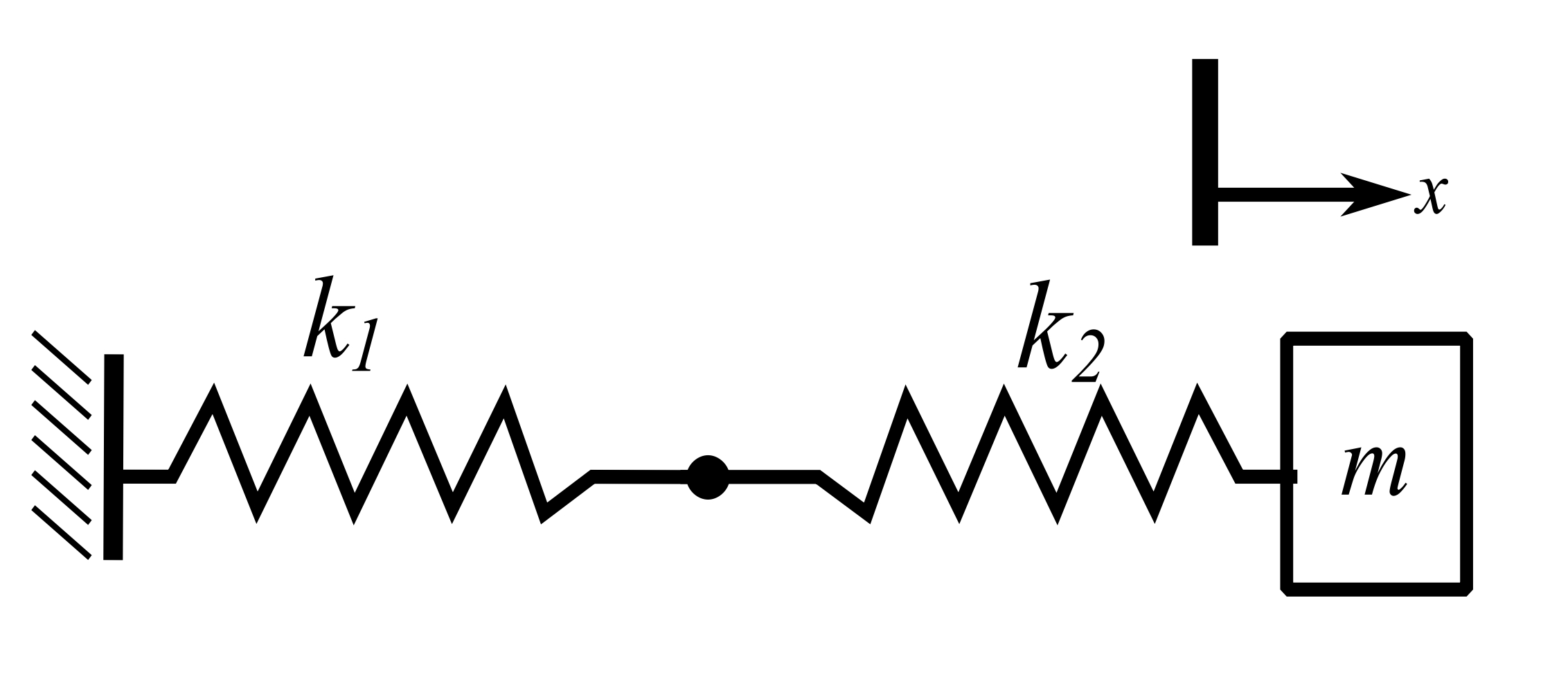

![]()
![]()
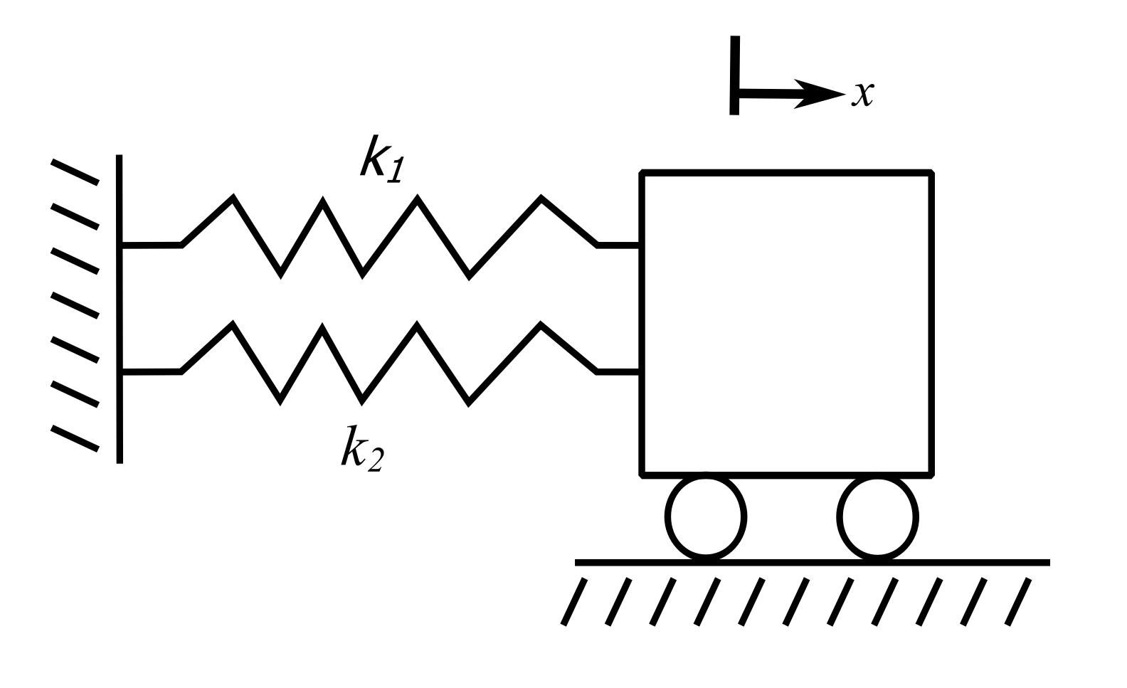
Springs in Parallel
Apply unit deflection, and calculate load.
![]()
Axially Loaded Bar
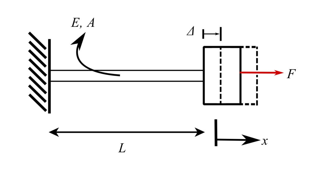
![]()
Therefore:
![]()
![]()
Therefore:
![]()
Inclined Axial Spring
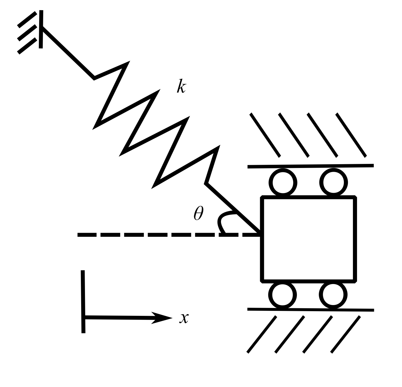
Apply a ![]() in the direction of motion.
in the direction of motion.
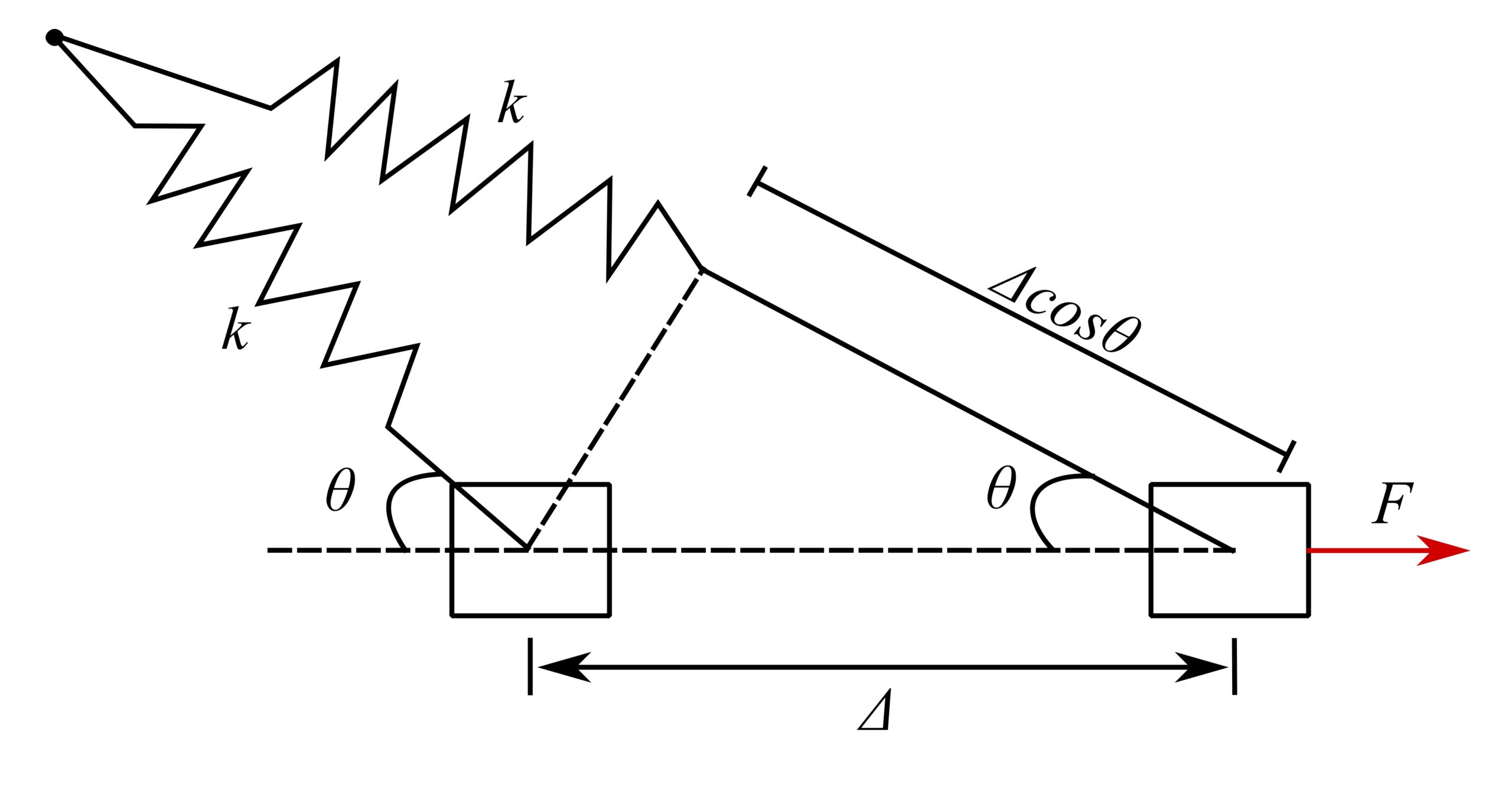
Therefore, force in spring when extended is ![]() , and thus:
, and thus:
![]()
Example 1
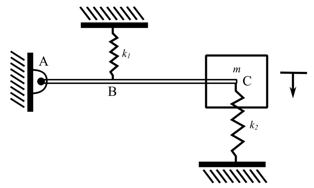
Stiffness
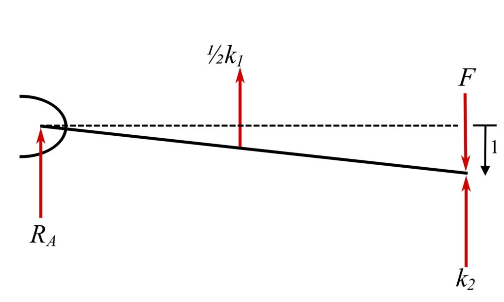
Apply unit deflection to ![]() and calculate the total load.
and calculate the total load.
![]()
![]()
Therefore:
![]()
If ![]() , then:
, then:
![]()
Example 2
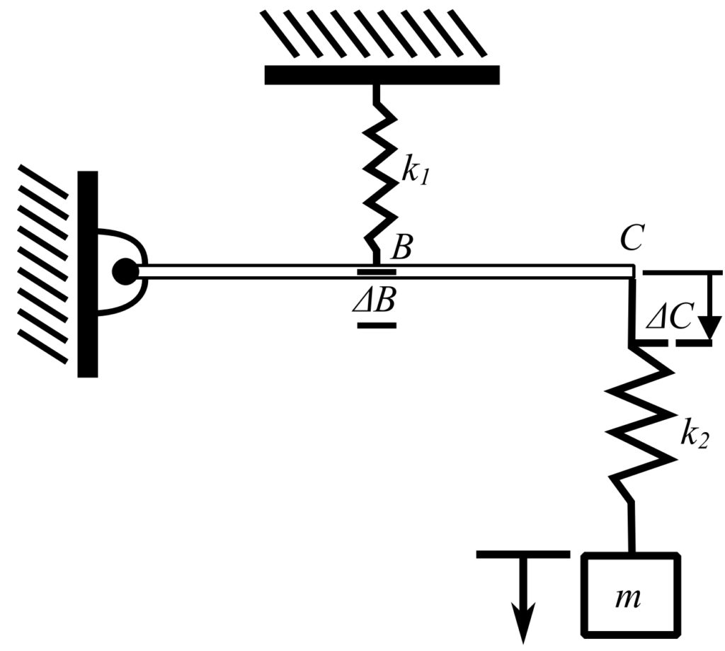
Flexibility
Apply unit load to ![]() and calculate the total deflection.
and calculate the total deflection.
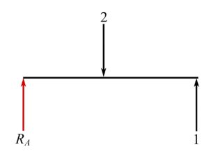
![]() , therefore:
, therefore:
![]()
Therefore :
![Rendered by QuickLaTeX.com \[\begin{split}\Delta \ \text{at} \ M &= \Delta_C + \frac{1}{k_2} \\&= \frac{4}{k_1} + \frac{1}{k_2}\end{split}\]](https://engcourses-uofa.ca/wp-content/ql-cache/quicklatex.com-eaad7219011104269c4ec235dfe809c3_l3.png)
Thus:
![Rendered by QuickLaTeX.com \[\begin{split}k_\text{eff} &= \frac{1}{\Delta}\\&= \frac{1}{\frac{4}{k_1}+\frac{1}{k_2}}\end{split}\]](https://engcourses-uofa.ca/wp-content/ql-cache/quicklatex.com-839ea7b7b22825732a371a8d15410a91_l3.png)
If ![]() , then:
, then:
![]()
Equivalent Spring Constant Equations
1.![]() axial springs in parallel
axial springs in parallel
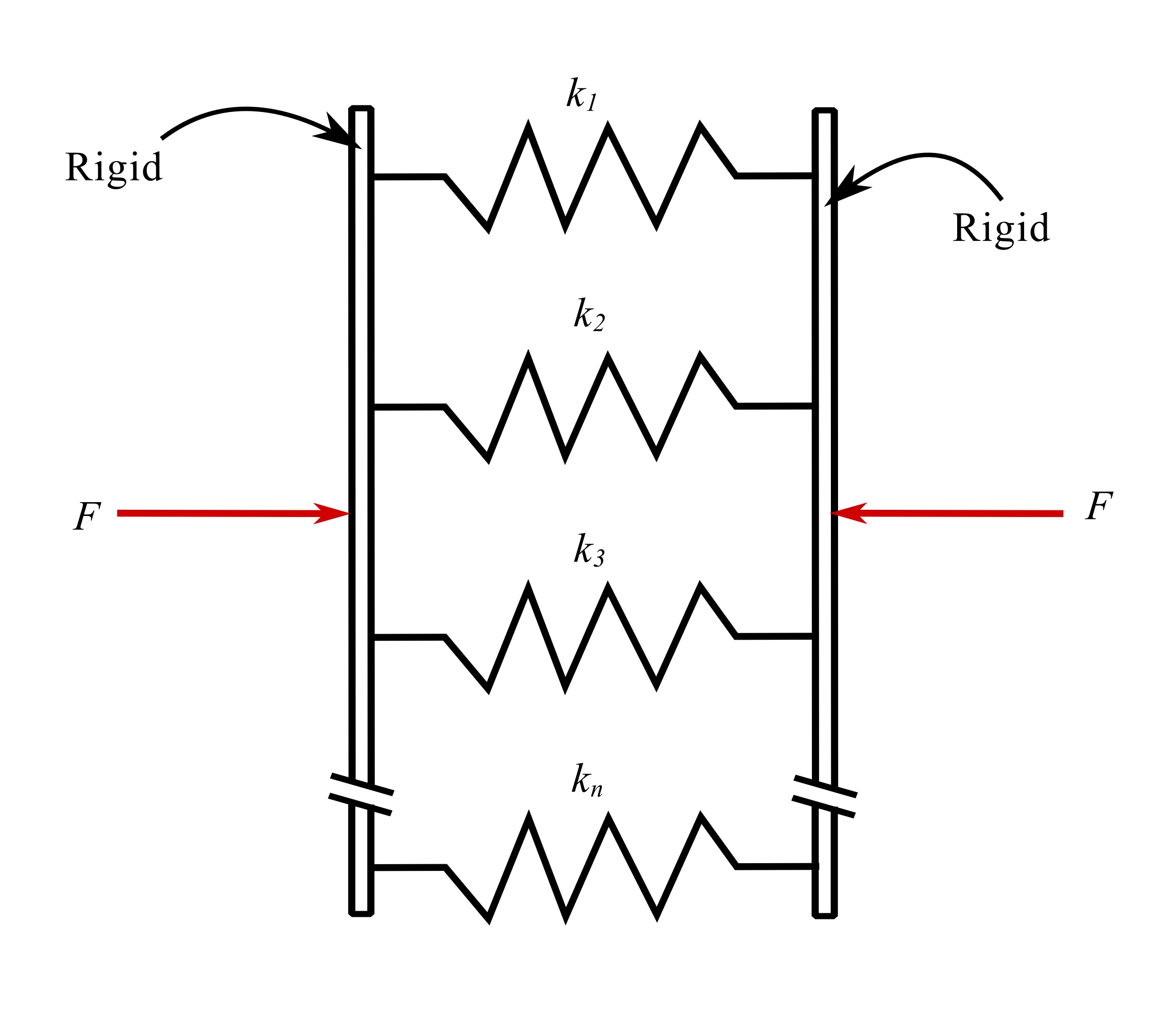
![]()
2.

![]()
3.Springs in parallel and series
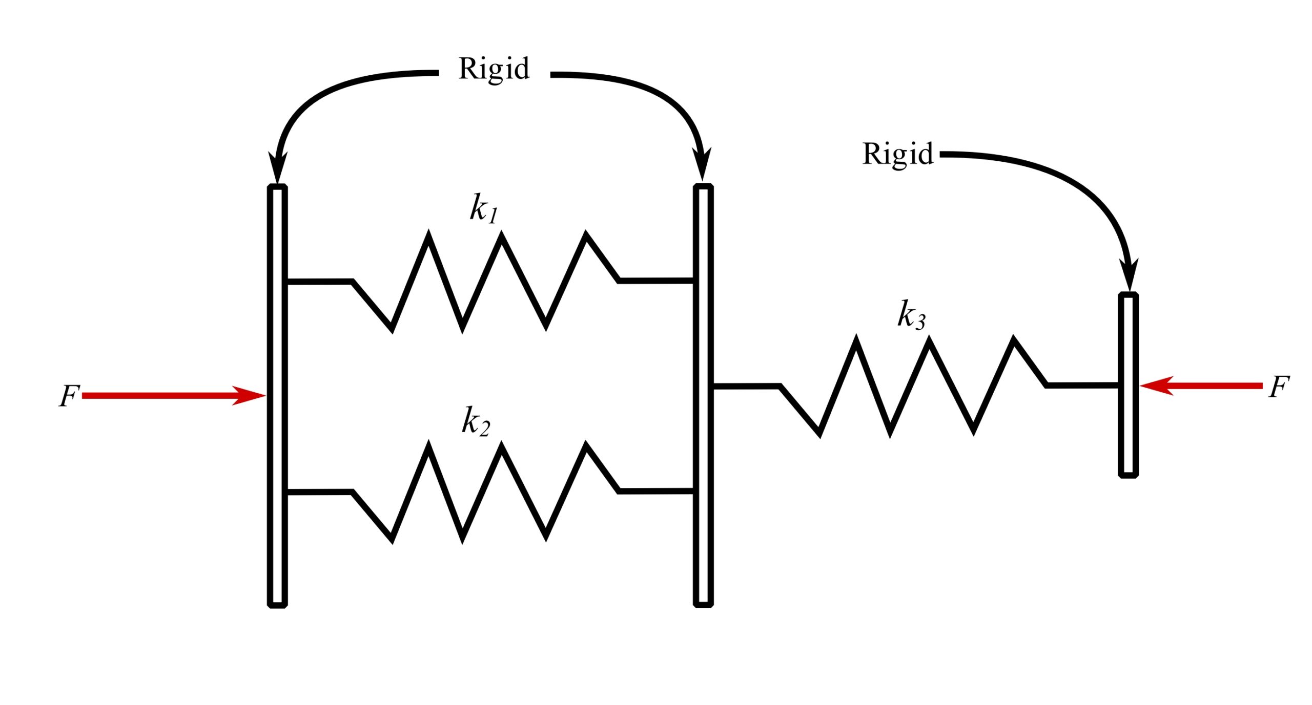
![]()
4.Inclined axial spring
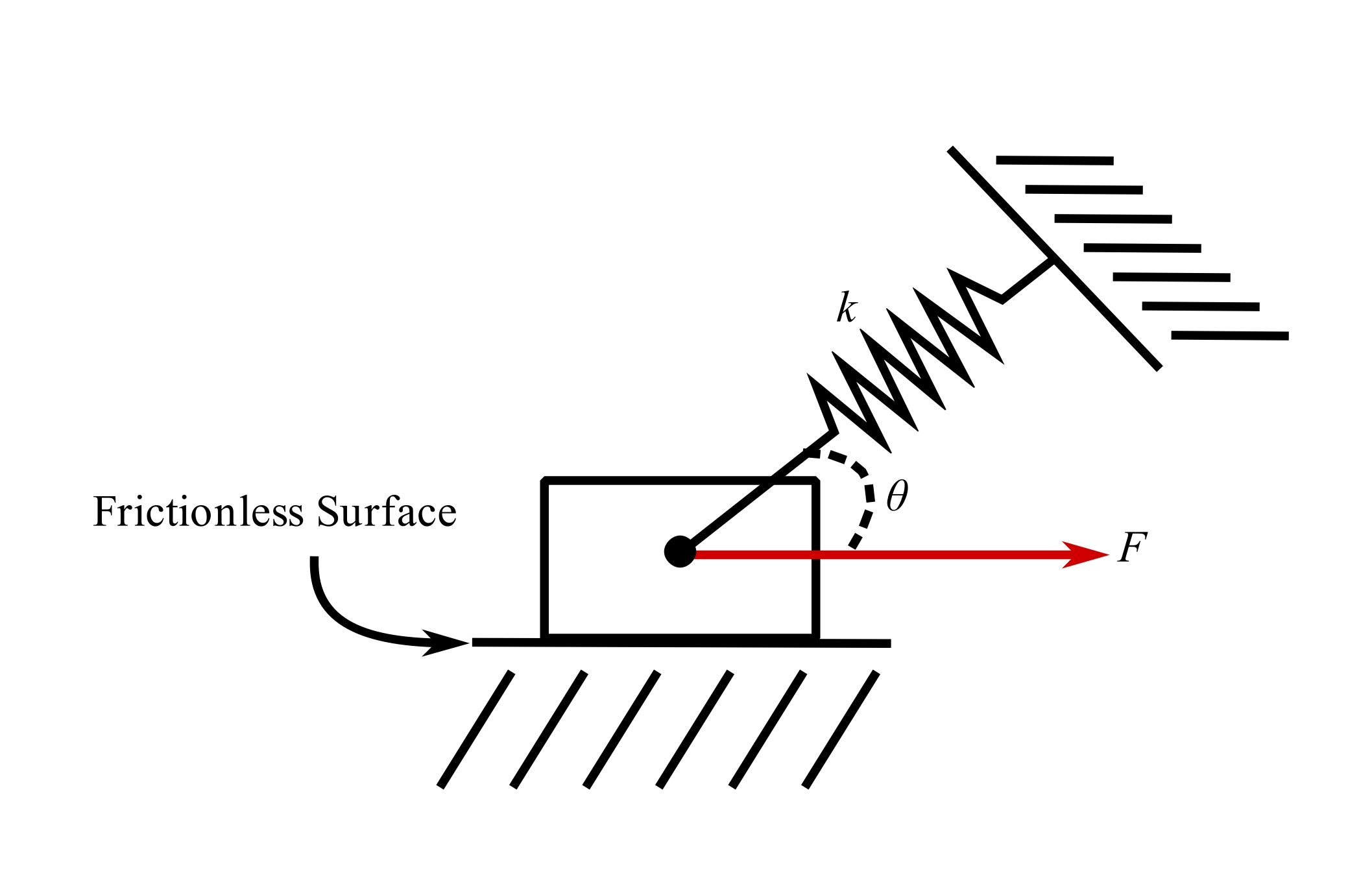
![]()
5.Rotating bar with spring support
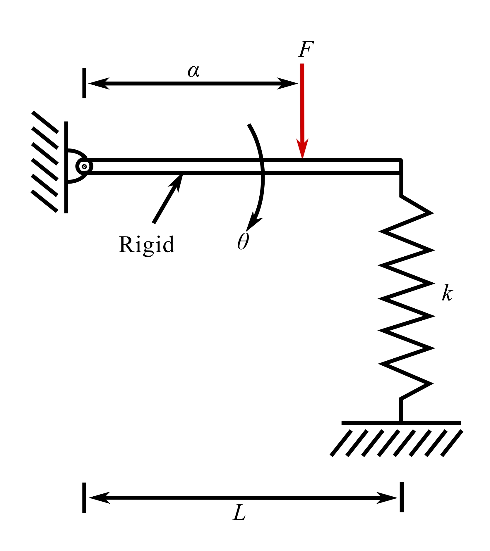
![]()
6.Rigid bar supported on two springs
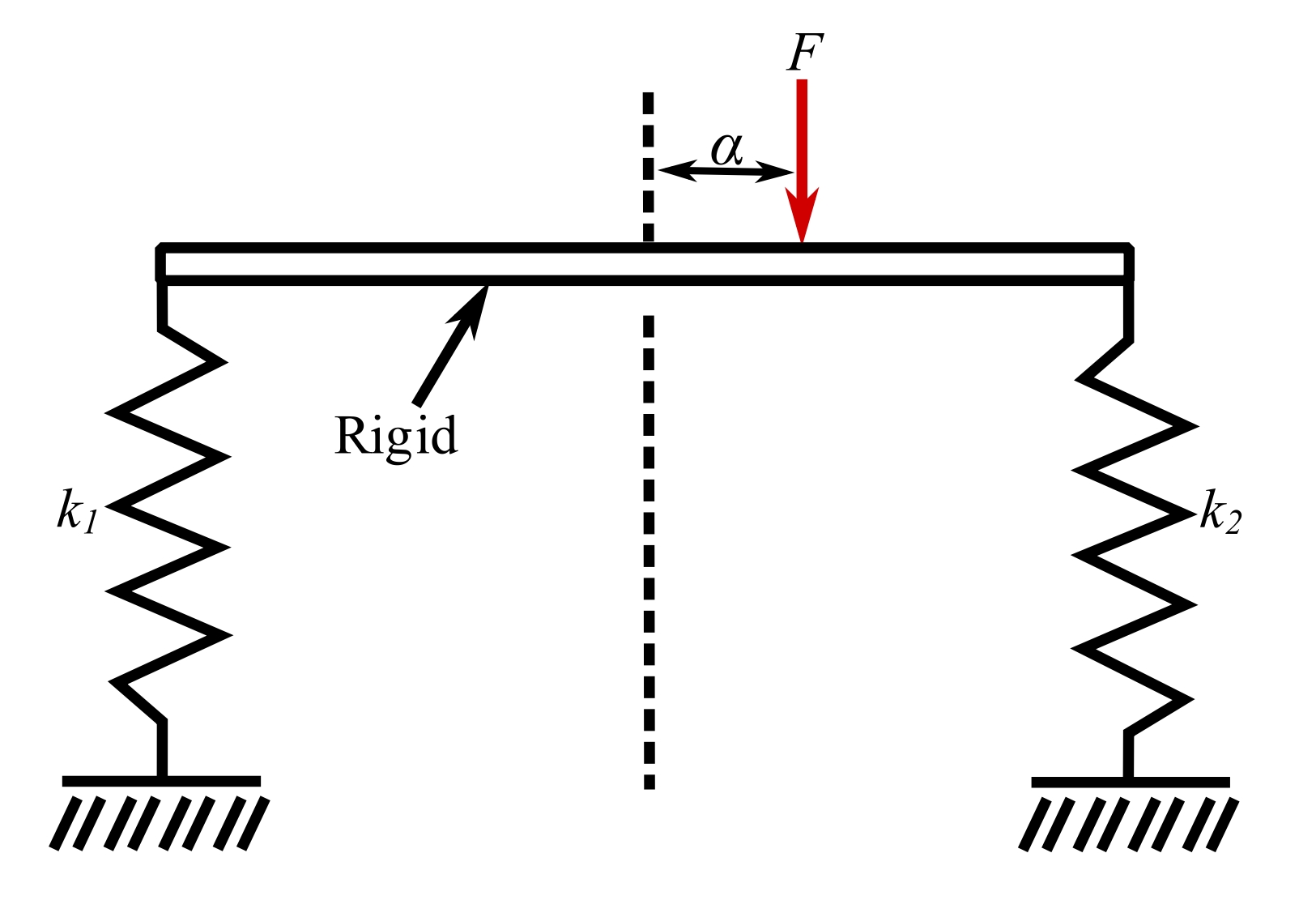
![]()
7.Rigid bar supported on three springs
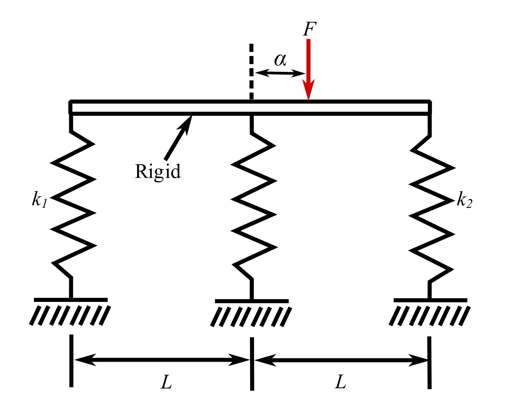
![]()
8.Axially loaded bar

![]()
Where ![]() is the cross-sectional area, and
is the cross-sectional area, and ![]() is the elastic modulus.
is the elastic modulus.
9.Axially loaded tapered bar
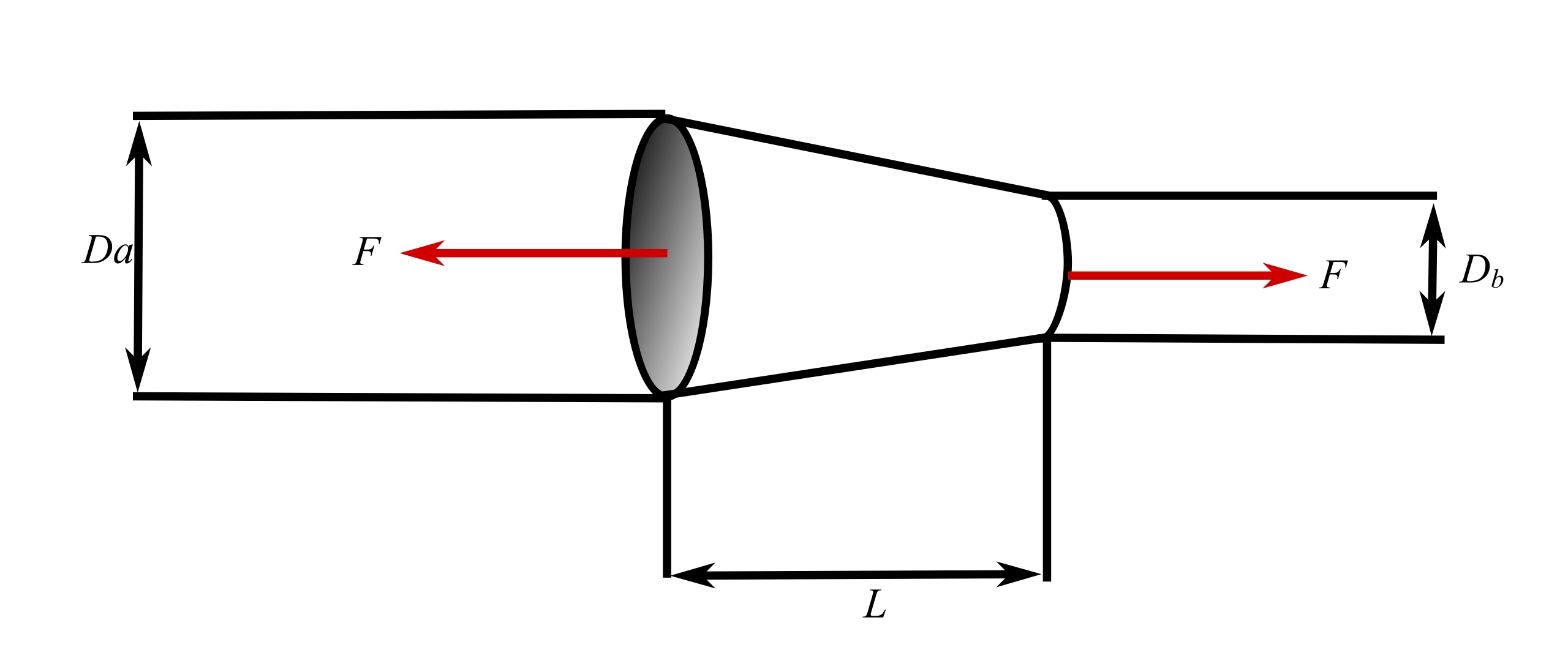
![]()
10.Axially helical spring
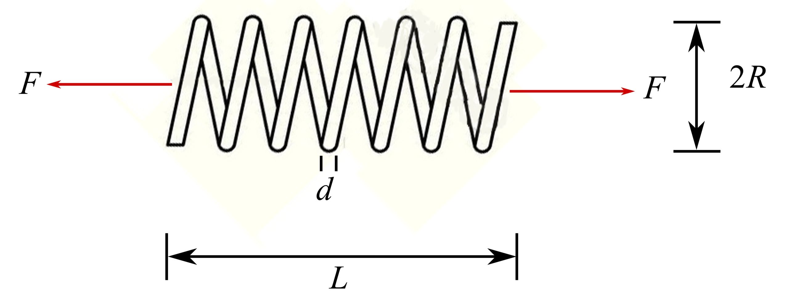
![]()
Where ![]() is the active number of turns, and
is the active number of turns, and ![]() is the elastic shear modulus.
is the elastic shear modulus.
11.Torsion of a uniform shaft
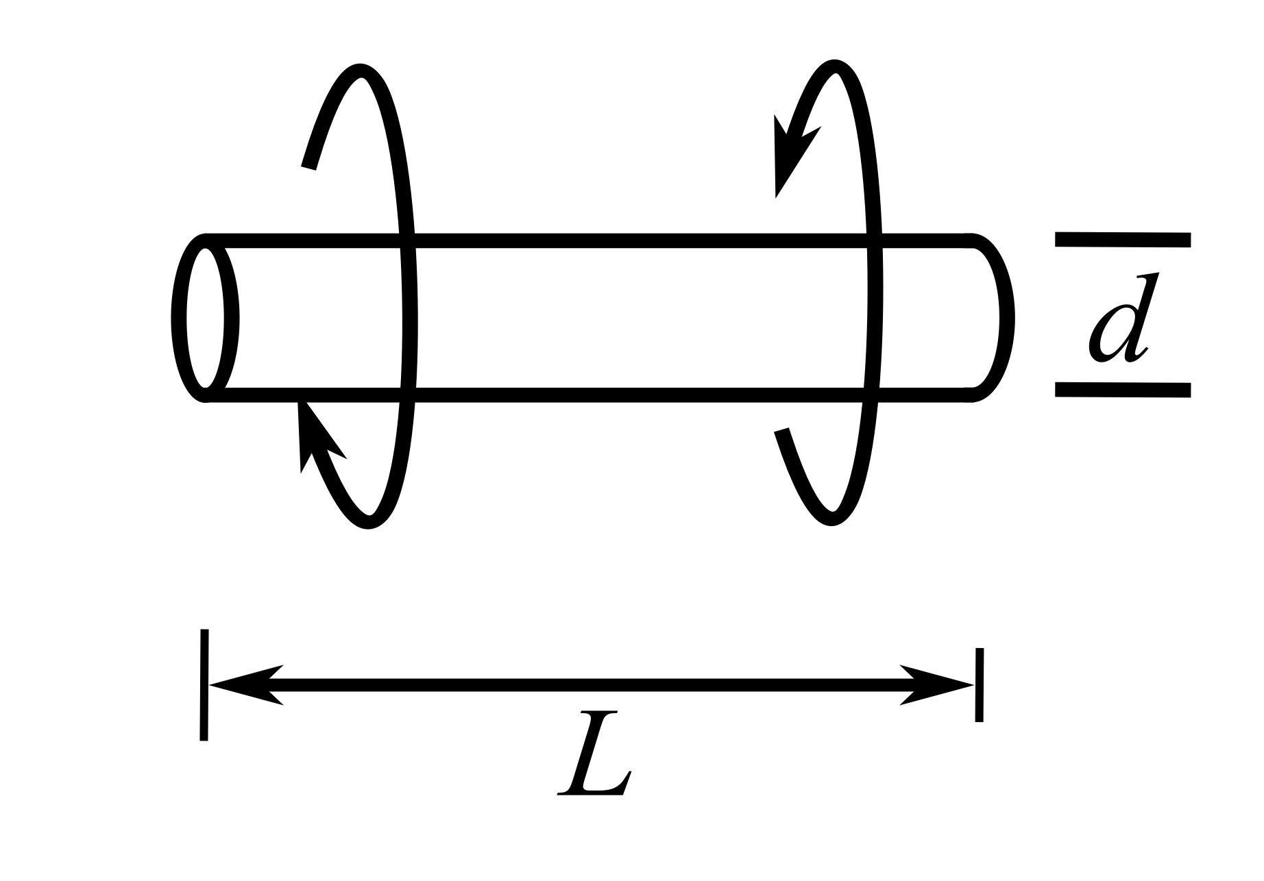
![]()
Where ![]() is the torsional constant of cross section (
is the torsional constant of cross section (![]() ).
).
12.Torsion of a tapered circular shaft
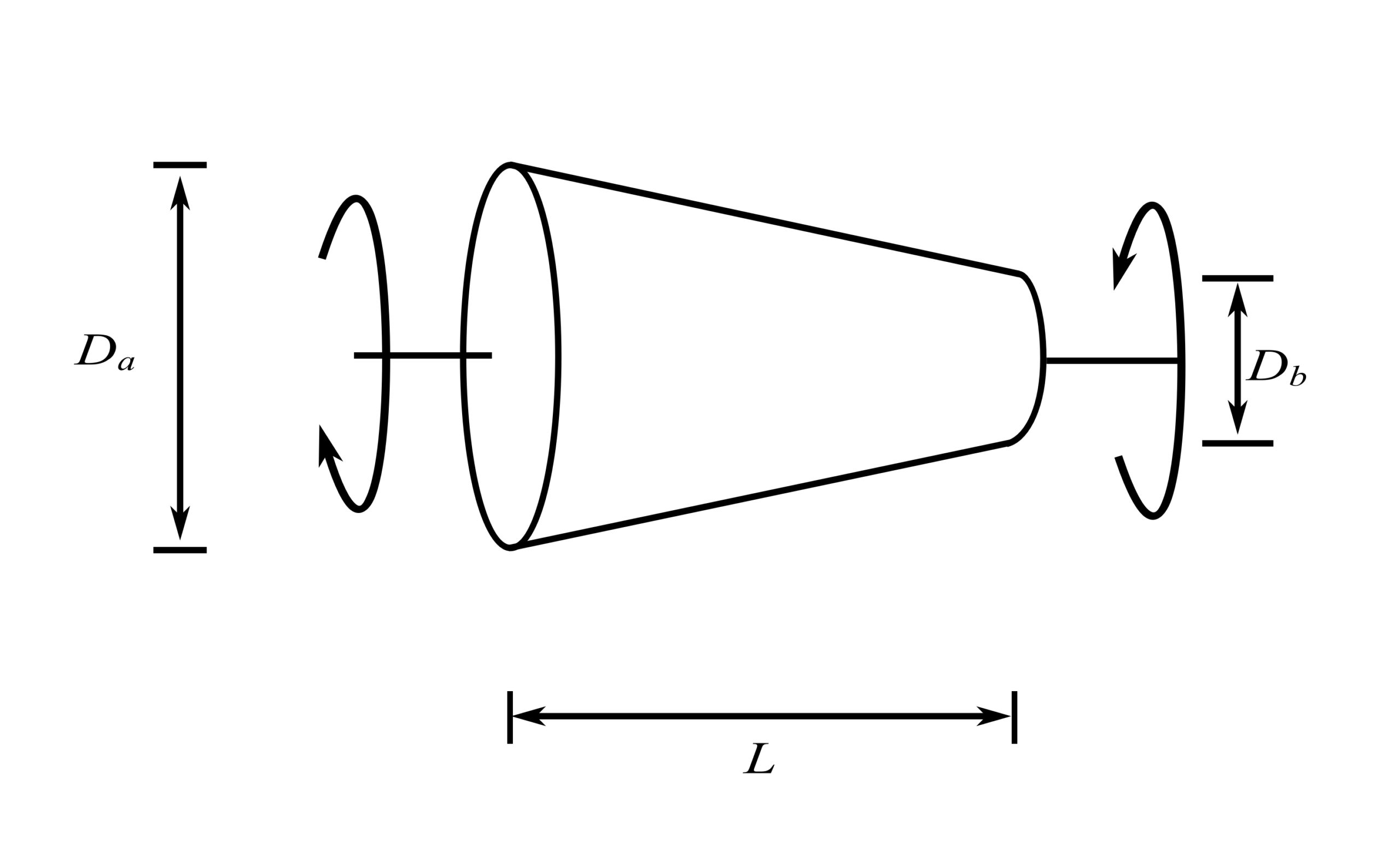
![]()
13.Spiral torsional spring
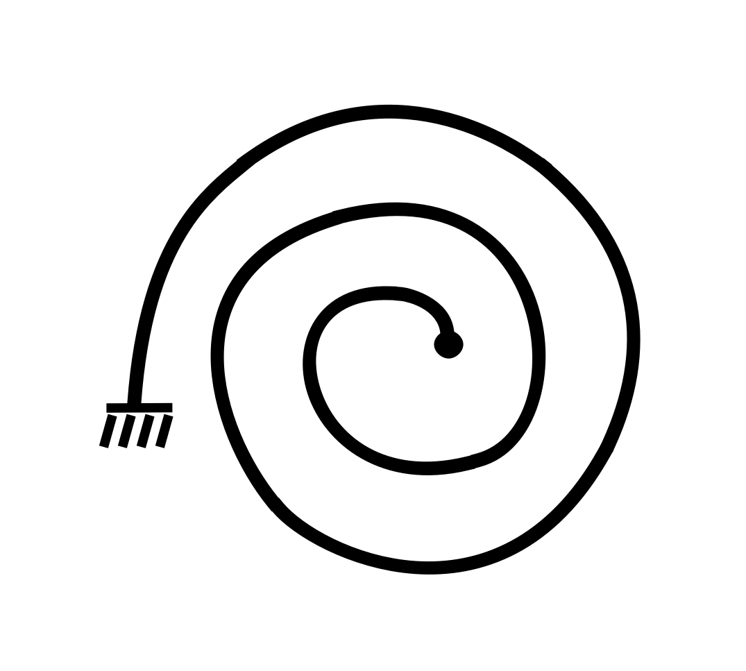
![]()
Where ![]() is Young’s modulus.
is Young’s modulus. ![]() is the moment of inertia of cross-sectional area, and
is the moment of inertia of cross-sectional area, and ![]() is the total length of the spiral.
is the total length of the spiral.
14.Cantilever bean, end load
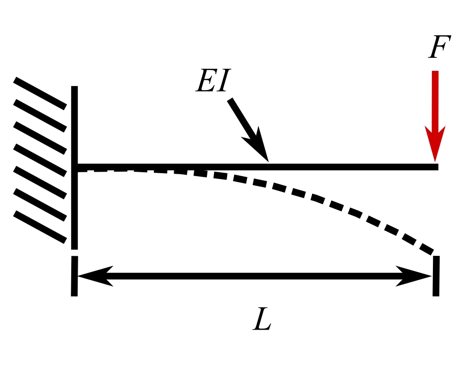
![]()
15.Simply supported bean, load at midspan
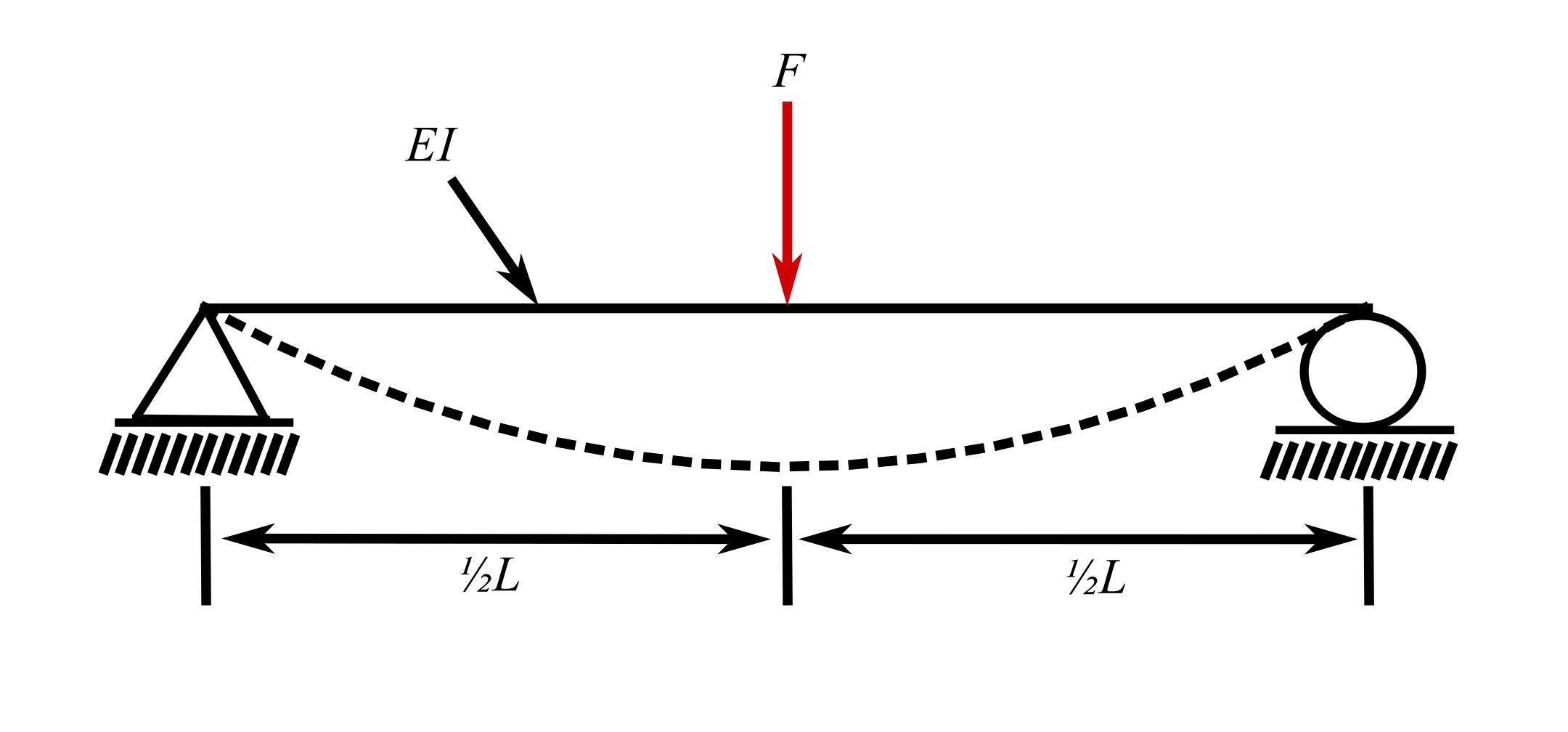
![]()
16.Simply supported bean, load anywhere between supports
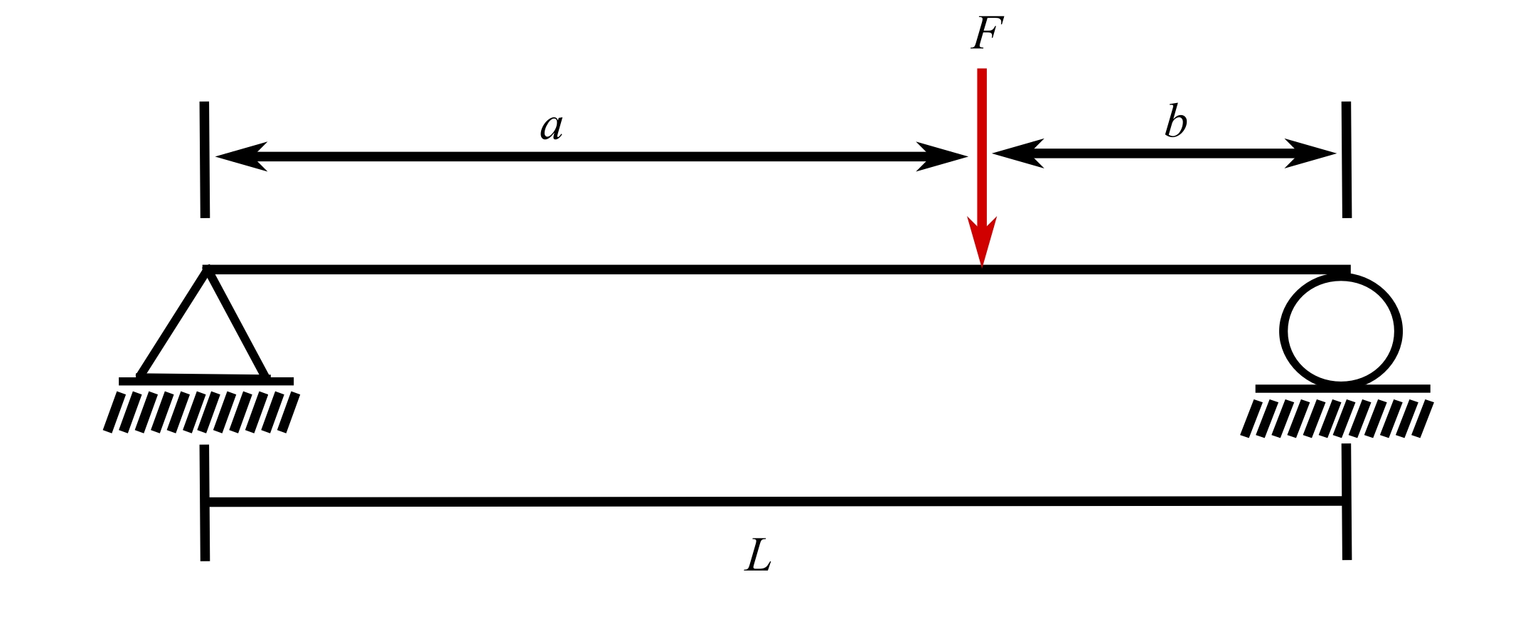
![]()
17.Fixed-fixed beam, load at midspan
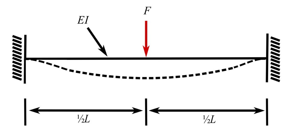
![]()
18.Fixed-fixed beam, off-center load
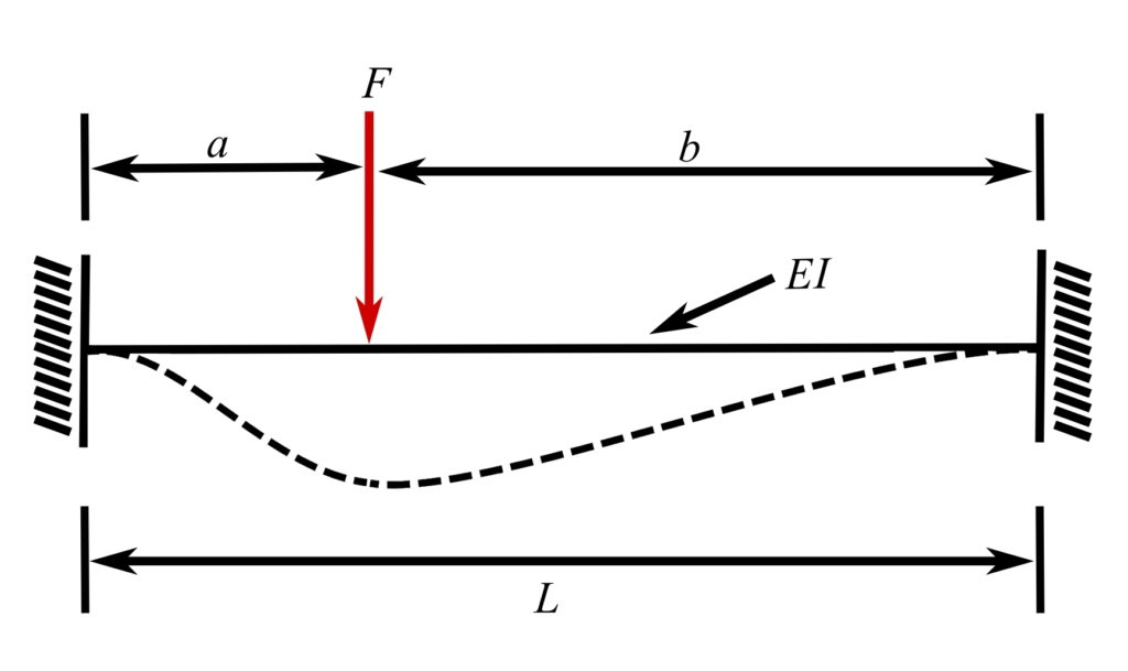
![]()
19.Propped cantilever, load at midspan
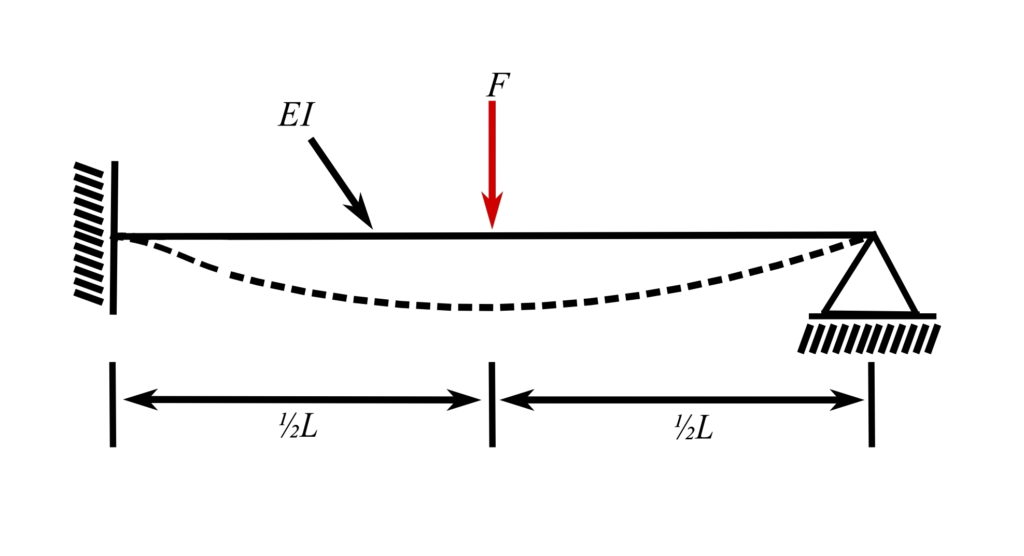
![]()
20.Propped cantilever, load at free end
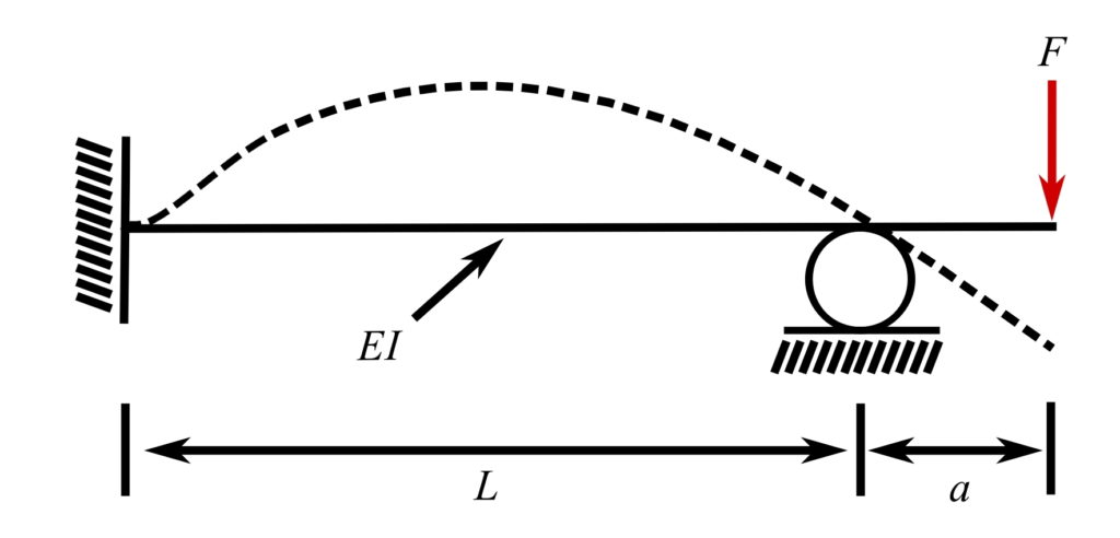
![]()
Fixed-fixed beam*
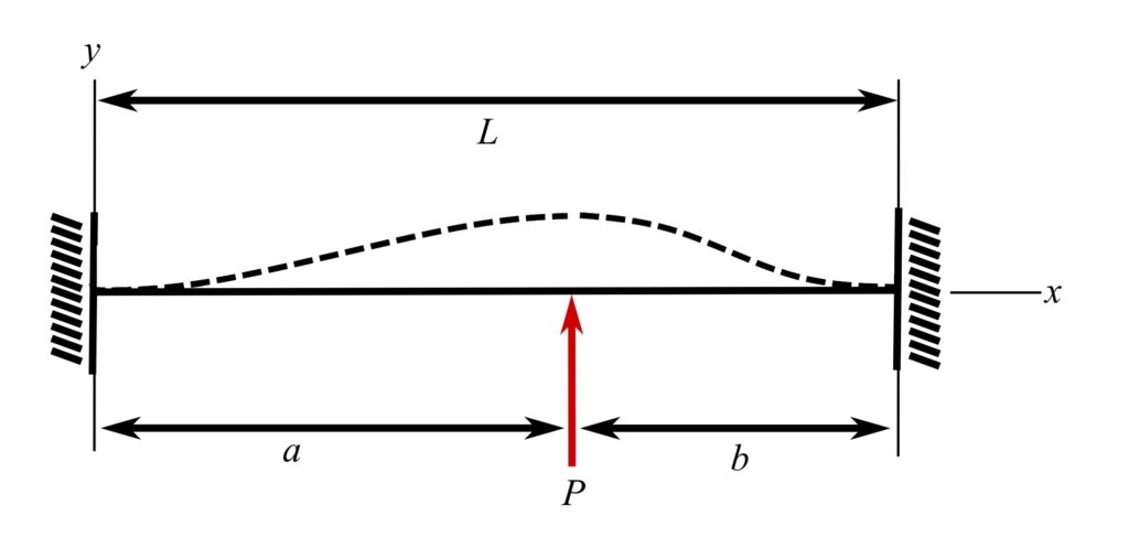
![]()
![]()
![]()
![]()
![]()
![]()
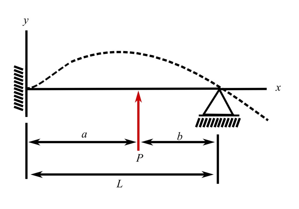
Fixed-pinned beam with overhang*
![]()
![]()
![]()
![]()
![]()
![]()
![]()
![]()
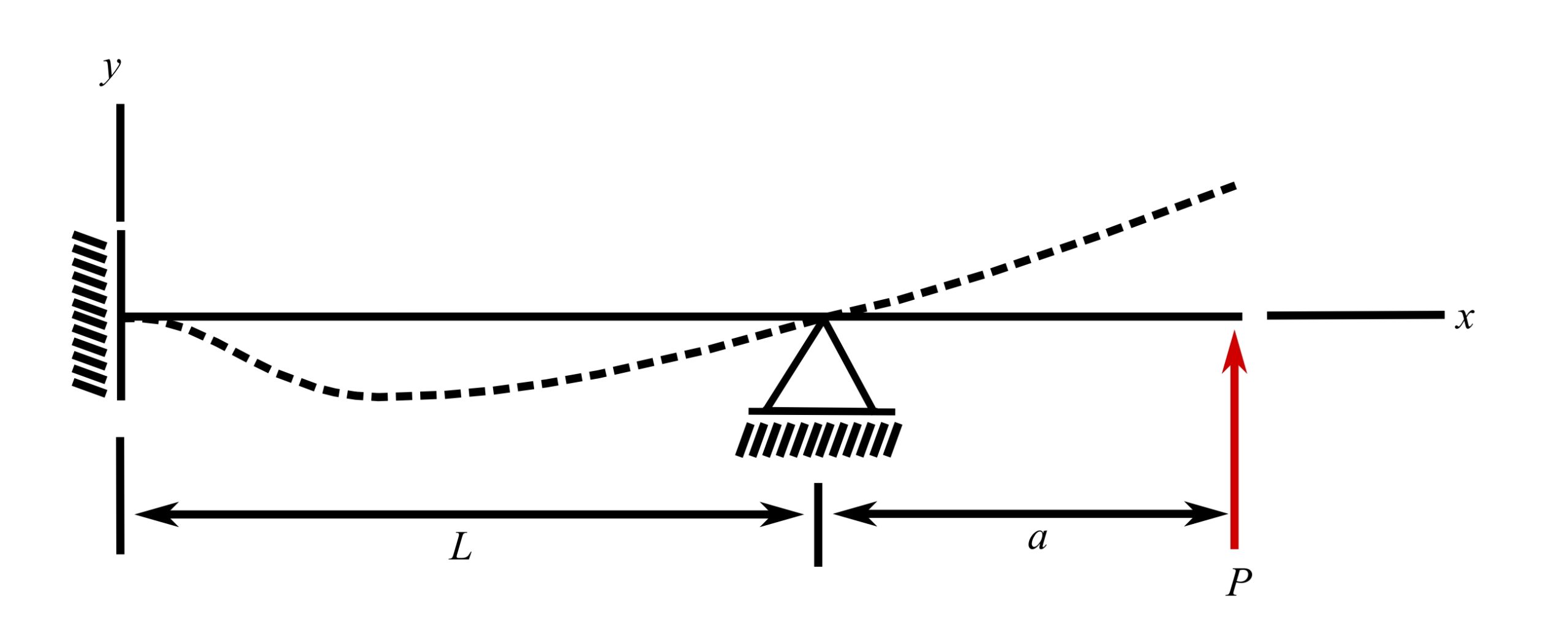
Fixed-pinned beam with overhang (P at x = l + a)*
![]()
![]()
![]()
![]()
![]()
Pinned-pinned beam with overhang*

![]()
![]()
Pinned-pinned beam with overhang (P at x = l + a)*

![]()
![]()
![]()
![]()
![]()
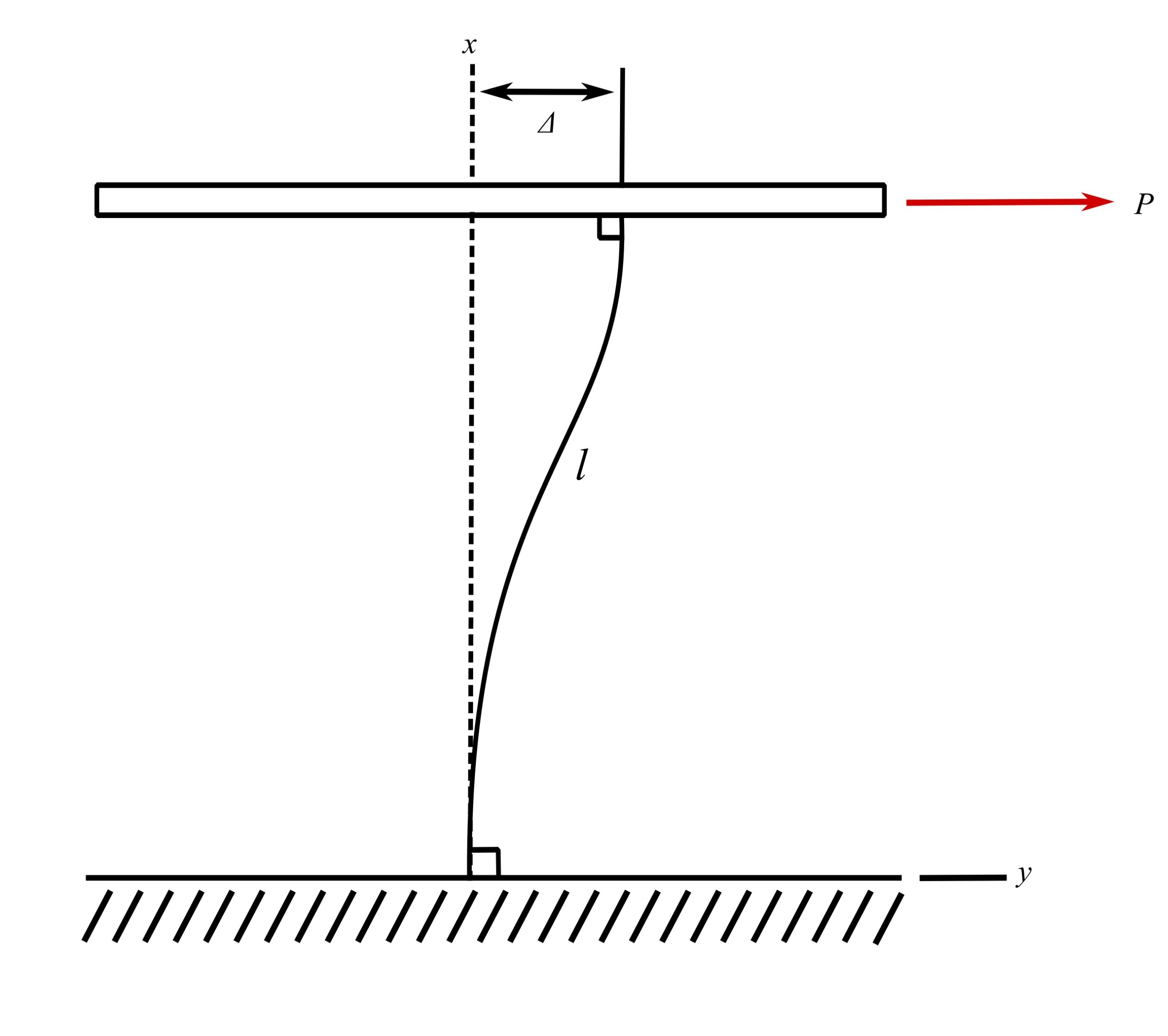
Fixed-fixed beam with lateral displacement
![]()
![]()
![]()
* Axial extensions due to axial end constraints considered negligible
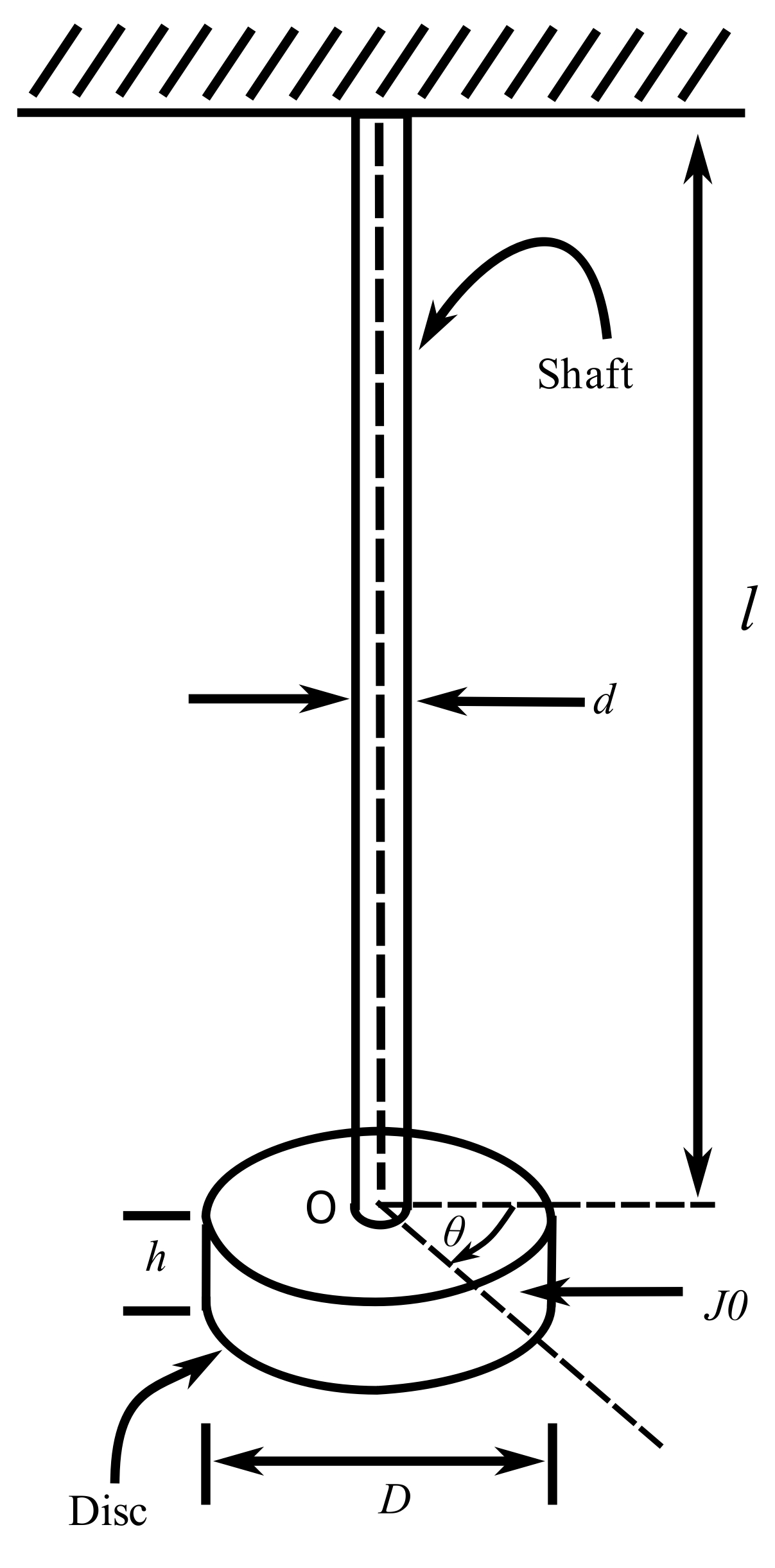
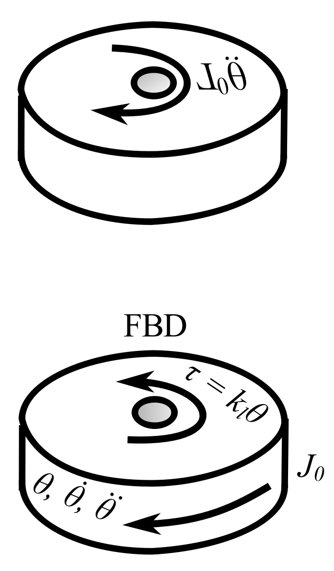
Torsional Oscillations
![]()
![]()
Let ![]() . From the strength of the material:
. From the strength of the material:
![]()
Where ![]() is the modulus of rigidity,
is the modulus of rigidity, ![]() is the angle of twist/unit length and
is the angle of twist/unit length and ![]() is the polar second moment of inertia. Therefore:
is the polar second moment of inertia. Therefore:
![]()
![]()
For soild circular cross sections:
![]()
