
Review of single and multi-degree of freedom (mdof) systems: Center of Percussion and Vibration of a Compound Pendulum
The concept of the center of percussion is usually discussed using the analysis of the changes in angular momentum and linear momentum associated with a body impacting a rotating object and essentially determining the point at which there is no change in acceleration at the pivot point due to this impact. (The usual example is a ball hitting a baseball or cricket bat.) For the compound pendulum shown the natural frequency is  where
where  is the moment of inertia of the body about the axis of rotation at
  . Instead of having a distributed mass, let the mass of the pendulum be concentrated at a single point located at a distance
  from the pivot point . The natural frequency of this simple pendulum is
  . If the natural frequencies of these two pendulums are the same, then the point at which
  is concentrated is called the center of oscillation and is identical to the center of percussion. If instead, we consider rotation about the center of oscillation (percussion) then the original pivot at becomes the center of percussion (oscillation).
Early automobile manufacturers did not realize this and as a result, cars had much more uncomfortable rides because impacts at one set of wheels (front or rear) were felt at the other. One of the first automobile designs to incorporate this idea was the very futuristic Chysler Airflow (circa 1930) which was years ahead in its design in a number of aspects. (So far ahead that it was a commercial failure.) For the illustration of the automobile shown the relationship between the position of the center of gravity and the positions of the front and rear wheels is given by  where
where  is the radius of gyration of the vehicle about its center of gravity and
  is the wheelbase (
 and
and  are the horizontal distances from the front and rear wheels to the center of gravity). From a vibration perspective if a car is designed with a mass distribution to meet these criteria (almost all recent automobiles are) then we can examine what happens at one set of wheels individually for certain situations (e.g. hitting a bump with the front wheels only).
Using the diagram below show that the condition for the center of percussion to be at the front wheels with the pivot at the rear wheels that  and that this is also true for the pivot point moving to the front wheels with the impact at the rear ones.
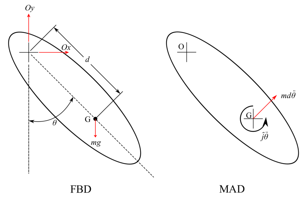
![\[J = m(r^*)^2\]](https://engcourses-uofa.ca/wp-content/ql-cache/quicklatex.com-0fdfb60e174564ab1bc79798b5f098ed_l3.png "Rendered by QuickLaTeX.com")
Where  is the moment of inertia about
  and is the radius of gyration about :
![\[\begin{split}+ \circlearrowleft \sum M_0 &= -mgd\theta \\&= J \ddot{\theta}+md\ddot{\theta}(d)\end{split}\]](https://engcourses-uofa.ca/wp-content/ql-cache/quicklatex.com-cf23986ed60a7a8d1e46c148df09d6ce_l3.png "Rendered by QuickLaTeX.com")
Therefore:
![\[(J+md^2)\ddot{\theta} + mgd\theta = 0\]](https://engcourses-uofa.ca/wp-content/ql-cache/quicklatex.com-0470d6ebf8b400fefbfd13c89bd9475b_l3.png "Rendered by QuickLaTeX.com")
![\[J_0 = J + md^2\]](https://engcourses-uofa.ca/wp-content/ql-cache/quicklatex.com-a7f5d3a99a96e10e61aca19e535b948e_l3.png "Rendered by QuickLaTeX.com")
Therefore:
![\[\begin{split}p &= \sqrt{\frac{mgd}{m(r^*)^2+md^2}} \\&= \sqrt{\frac{gd}{(r^*)^2+d^2}}\end{split}\]](https://engcourses-uofa.ca/wp-content/ql-cache/quicklatex.com-a40c5b7450c4be323d4372f93eef73cb_l3.png "Rendered by QuickLaTeX.com")
Equivalent Pendulum
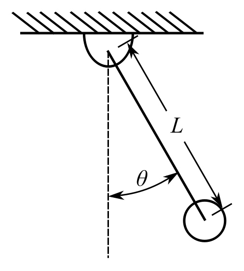
![\[p = \sqrt{\frac{g}{L}}\]](https://engcourses-uofa.ca/wp-content/ql-cache/quicklatex.com-514efd0b2f8eb5db01e99baef16d04aa_l3.png "Rendered by QuickLaTeX.com")
Therefore choose:
![\[L = \frac{(r^*)^2+d^2}{d}\]](https://engcourses-uofa.ca/wp-content/ql-cache/quicklatex.com-3027766bf440792dd02d35dee7f48caa_l3.png "Rendered by QuickLaTeX.com")
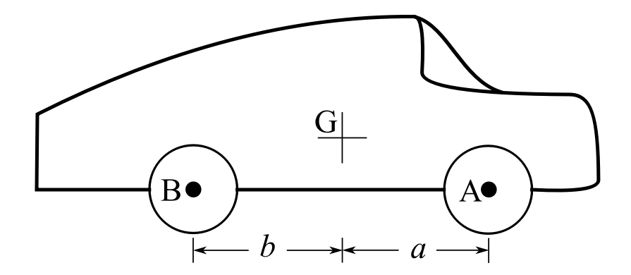
![\[ \ell = a+b \]](https://engcourses-uofa.ca/wp-content/ql-cache/quicklatex.com-e95bc09846ba67f00b39750f914bcb93_l3.png "Rendered by QuickLaTeX.com")
For application to the auto above  (wheelbase). For rotation about
  :
:
![\[d = b\]](https://engcourses-uofa.ca/wp-content/ql-cache/quicklatex.com-a7a81acc00c857de68702be9be642252_l3.png "Rendered by QuickLaTeX.com")
Therefore:
![\[\begin{split} L &= a+b \\&= \frac{(r^*)^2+b^2}{b} \\&= \frac{(r^*)^2}{b} +b \end{split}\]](https://engcourses-uofa.ca/wp-content/ql-cache/quicklatex.com-4177af456b10f732a966b4d8a0f09e1a_l3.png "Rendered by QuickLaTeX.com")
Therefore:
![\[r^* = \sqrt{ab}\]](https://engcourses-uofa.ca/wp-content/ql-cache/quicklatex.com-07f883baac24142cbec23ea76af77b79_l3.png "Rendered by QuickLaTeX.com")
For rotation about  :
:
![\[d = a\]](https://engcourses-uofa.ca/wp-content/ql-cache/quicklatex.com-ee2ebf51de6513c1e6a3e110efcb00f4_l3.png "Rendered by QuickLaTeX.com")
Therefore:
![\[a+b = \frac{(r^*)^2}{a} +a \]](https://engcourses-uofa.ca/wp-content/ql-cache/quicklatex.com-e883f80c4f2fc5cc87a9bbd988694368_l3.png "Rendered by QuickLaTeX.com")
Determination of Damping Ratio
We know that for any SDOF viscously damped system the equation for free vibration is:
![\[m_e\ddot{x} + C_e\dot{x} + k_ex = 0\]](https://engcourses-uofa.ca/wp-content/ql-cache/quicklatex.com-92bb583d2c4d71273a4e6a51d4dd8de0_l3.png "Rendered by QuickLaTeX.com")
and the system parameters are the natural frequency:
![\[p = \sqrt{\frac{k_e}{m_e}}\]](https://engcourses-uofa.ca/wp-content/ql-cache/quicklatex.com-372c16d198b5107a1bbbf55f48e769e1_l3.png "Rendered by QuickLaTeX.com")
and the damping ratio:
![\[\zeta = \frac{C_e}{C_c} = \frac{Ce}{Z_{mep}}\]](https://engcourses-uofa.ca/wp-content/ql-cache/quicklatex.com-227129273a9013300847e0dd0981d6b3_l3.png "Rendered by QuickLaTeX.com")
We can determine the damping ratio from how rapidly the vibration decays. To do this we use the so-called logarithmic decrement. Consider the damped response:
![\[ x(t) = e^{-\zeta pt}\big[X\sin{(\sqrt{1-\zeta^2}pt+\phi)}\big]\]](https://engcourses-uofa.ca/wp-content/ql-cache/quicklatex.com-689f8174b75ed65eab3a41972b324ab4_l3.png "Rendered by QuickLaTeX.com")
which for  looks like:
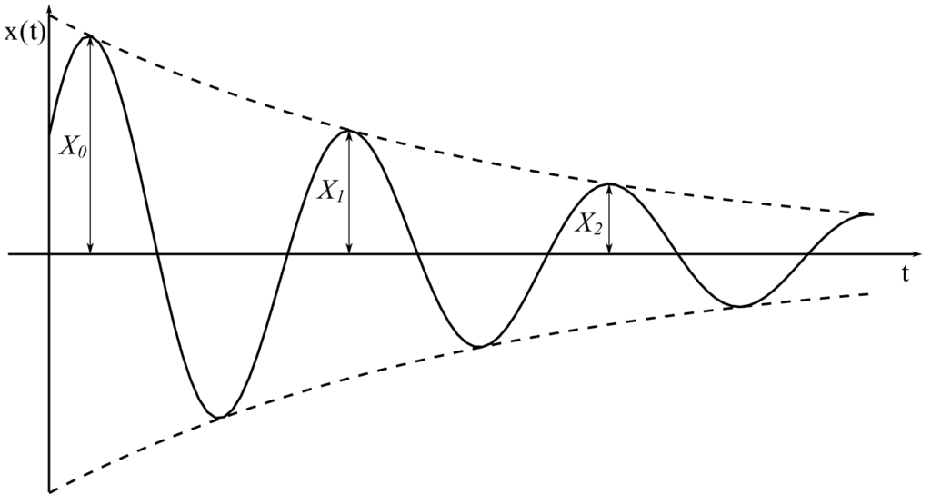
These peaks occur approximately when:
![\[\sin{\big(\sqrt{1 - \zeta^2}pt + \phi\big)} = 1\]](https://engcourses-uofa.ca/wp-content/ql-cache/quicklatex.com-158e90a0889057e1a761fb47b9adcd75_l3.png "Rendered by QuickLaTeX.com")
Therefore if the first occurs at  then the next time it is at:
![\[t_1 = t_0 + \frac{2\pi}{p\sqrt{1-\zeta^2}}\]](https://engcourses-uofa.ca/wp-content/ql-cache/quicklatex.com-23aacb4d049b39717e5d9e2da809a436_l3.png "Rendered by QuickLaTeX.com")
Therefore:
![\[\begin{split} \frac{X_0}{X_1} &= \frac{e\strut^{-\zeta pt_0}X}{e\strut^{-\zeta pt_1}X} \\&= \frac{e\strut^{-\zeta pt_0}} {e\strut^{-\zeta p\big(t_0 + \frac{2\pi}{p \sqrt{1-\zeta^2}}\big)}} \\&= e\strut^{\frac{2\pi\zeta}{\sqrt{1-\zeta^2}}} \end{split}\]](https://engcourses-uofa.ca/wp-content/ql-cache/quicklatex.com-e16736804588b404be9bcae6b2d43a16_l3.png "Rendered by QuickLaTeX.com")
and this is the same ratio for  ,
,  , etc.
Therefore this creates the logarithmic decrement equation:
![\[ \begin{split} \ln{\frac{X_0}{X_1}} &= \frac{2\pi\zeta}{\sqrt{1-\zeta^2}} \\&\equiv \delta \end{split}\]](https://engcourses-uofa.ca/wp-content/ql-cache/quicklatex.com-afeaa71e052d96c85b0c0bdbfeec9f31_l3.png "Rendered by QuickLaTeX.com")
If we take n cycles:
![\[\frac{X_0}{X_n} = \frac{X_0}{X_1}\frac{X_1}{X_2}\frac{X_2}{X_3}..... \frac{X_{n-1}}{X_n}\]](https://engcourses-uofa.ca/wp-content/ql-cache/quicklatex.com-e37bcff7eb72a03c62041a7da36cf91c_l3.png "Rendered by QuickLaTeX.com")
![\[\begin{split}\ln {\frac{X_0}{X_n}} &= \ln {\frac{X_0}{X_1}} + \ln {\frac{X_1}{X_2}}..... \\&= n\frac{2\pi\zeta}{\sqrt{1-\zeta^2}} \\&= n\delta \end{split}\]](https://engcourses-uofa.ca/wp-content/ql-cache/quicklatex.com-d60dd0bee3644cb217237d629a0d0a77_l3.png "Rendered by QuickLaTeX.com")
Therefore:
![\[\begin{split} \delta &= \frac{1}{n}\ln{\frac{X_0}{X_n}} \\&= \frac{2\pi\zeta}{\sqrt{1-\zeta^2}} \end{split}\]](https://engcourses-uofa.ca/wp-content/ql-cache/quicklatex.com-143ca151523149e778e96bc239a9f2ec_l3.png "Rendered by QuickLaTeX.com")
Therefore if we measure  we can easily determine the damping ratio
  .
.
If 
| 0.05 | 0.1 | 0.2 | 0.3 | 0.4 | 0.5 |
 | 1.37 | 1.87 | 3.61 | 7.21 | 15.5 | 37.6 |
It does not take a large to quickly damp out vibrations.