
Review of single and multi-degree of freedom (mdof) systems: Equivalent spring constants
One of the components we need in these equations of motion is the spring constant  . We can often find this for a system using static techniques. This is easily generalized for MDOF systems.
For SDOF systems, we can imagine the static response of the system using one of the approaches:
1.Apply a unit force (moment) to the mass (inertia) in the positive direction of motion then calculate the displacement that occurs (flexibility approach).
![\[k = \frac{\text{force (moment) in direction of motion}}{\text{displacement (rotation) in direction of motion}}\]](https://engcourses-uofa.ca/wp-content/ql-cache/quicklatex.com-19c29361b53c8287f1b6a4550bcb475e_l3.png "Rendered by QuickLaTeX.com")
2.Apply a unit displacement (rotation) to the mass (inertia) in the positive direction of motion then calculate the force (moment) required to maintain it (stiffness approach).
It depends on the situation to determine the best one to use. Generally, for a series situation, use flexibility, while for parallel, use stiffness.
Springs in Series
Apply unit load, and calculate total deflection.
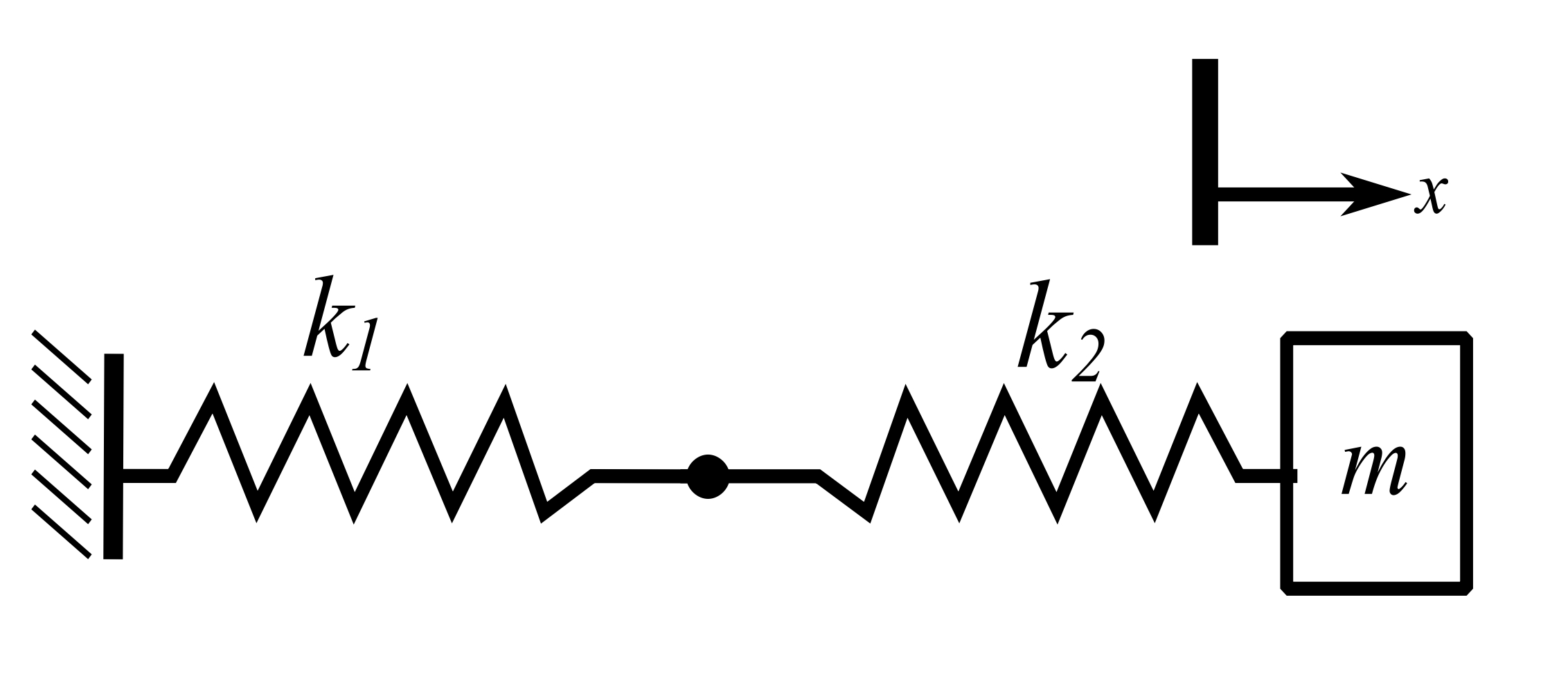
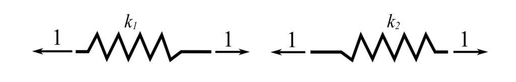
![\[\Delta_1 = \frac{1}{k_1} \ \ \Delta_2 = \frac{1}{k_2} \ \ \Delta_\text{total} = \frac{1}{k_1} + \frac{1}{k_2}\]](https://engcourses-uofa.ca/wp-content/ql-cache/quicklatex.com-21710329b7e75c2f80b73e10d9d1f879_l3.png "Rendered by QuickLaTeX.com")
![\[k_\text{eff} = \frac{1}{\frac{1}{k_1} + \frac{1}{k_2}} = \frac{k_1k_2}{k_1+k_2}\]](https://engcourses-uofa.ca/wp-content/ql-cache/quicklatex.com-a0720eb013a17f75653551f438277886_l3.png "Rendered by QuickLaTeX.com")
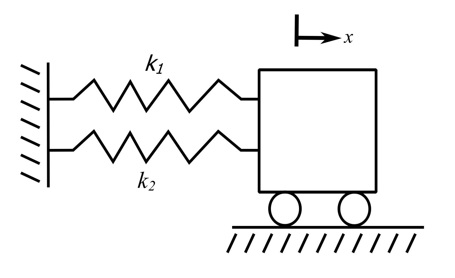
Springs in Parallel
Apply unit deflection, and calculate load.
![\[k_\text{eff} = k_1 + k_2\]](https://engcourses-uofa.ca/wp-content/ql-cache/quicklatex.com-c26519648928a88af4237c0fa1cefb34_l3.png "Rendered by QuickLaTeX.com")
Axially Loaded Bar
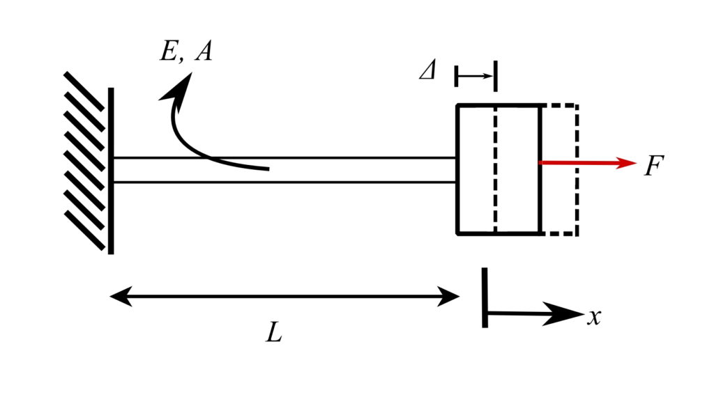
![\[\text{Stress} = E \cdot \text{Strain}\]](https://engcourses-uofa.ca/wp-content/ql-cache/quicklatex.com-641e91016065356e6d829c498b895930_l3.png "Rendered by QuickLaTeX.com")
Therefore:
![\[\sigma = \frac{F}{A} \equiv \Delta = E\epsilon = E \cdot \frac{\Delta}{L}\]](https://engcourses-uofa.ca/wp-content/ql-cache/quicklatex.com-5eb99839091a2204393fdbc89a9fe3b4_l3.png "Rendered by QuickLaTeX.com")
![\[F = \frac{EA\Delta}{L}\]](https://engcourses-uofa.ca/wp-content/ql-cache/quicklatex.com-17b94c72f6545ab02a5a16c453cbc397_l3.png "Rendered by QuickLaTeX.com")
Therefore:
![\[k_e = \frac{EA}{L}\]](https://engcourses-uofa.ca/wp-content/ql-cache/quicklatex.com-60b79d8a16a3641c59af6a5d3113d9d8_l3.png "Rendered by QuickLaTeX.com")
Inclined Axial Spring
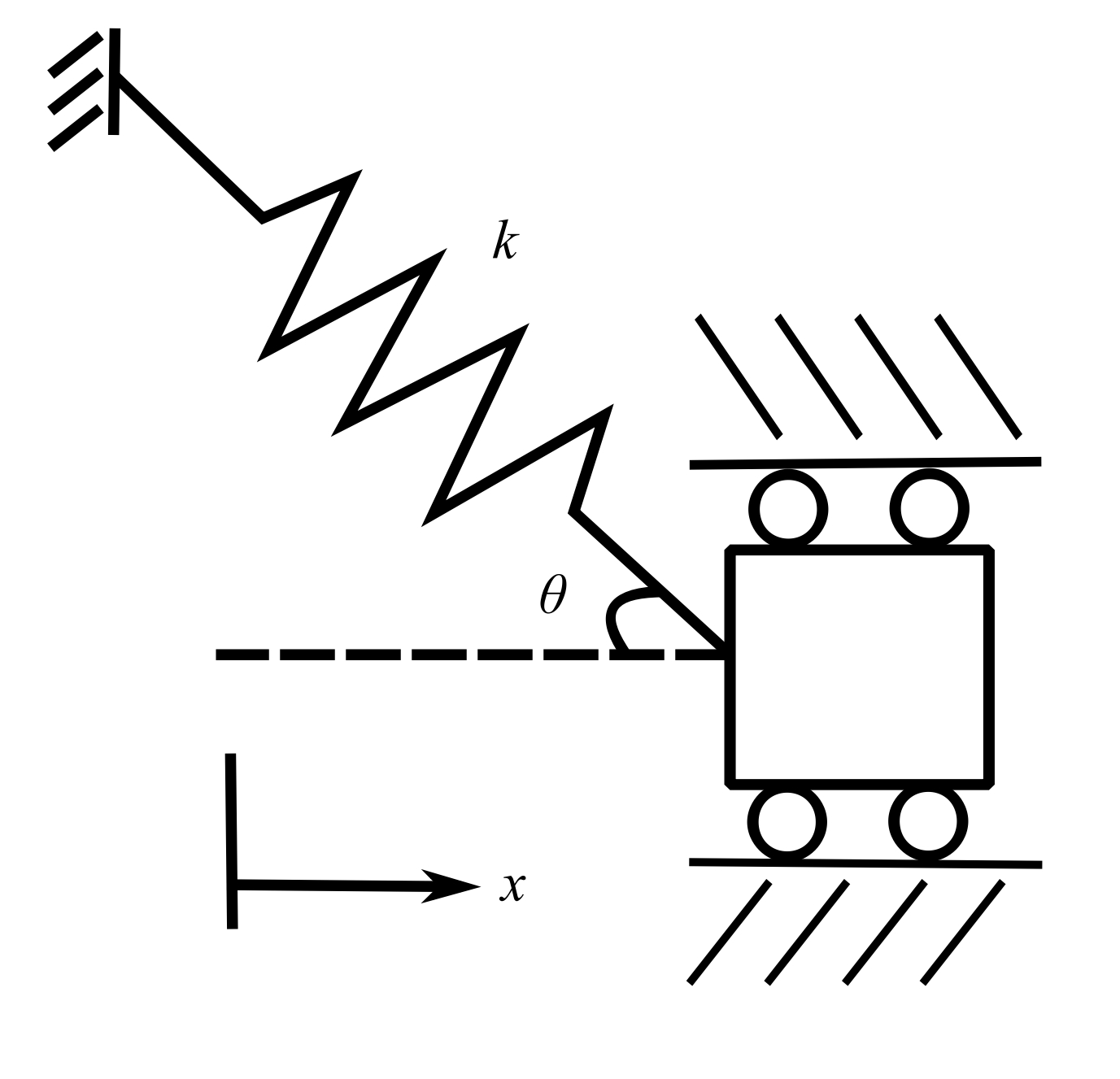
Apply a  in the direction of motion.
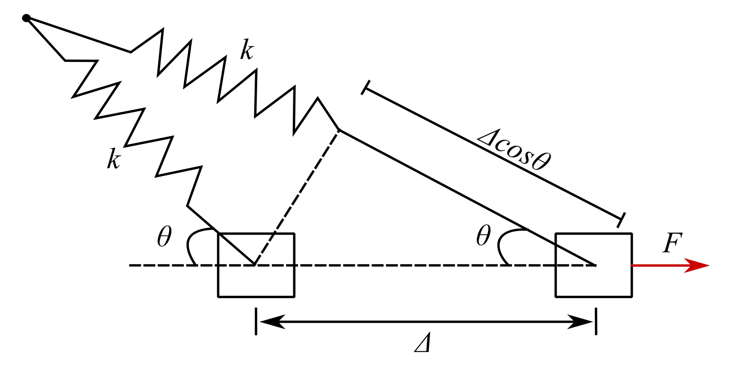
Therefore, force in spring when extended is  , and thus:
![\[\frac{\text{Force in direction of motion}}{\Delta \ \text{in direction of motion}} = \frac{(k\Delta\cos\theta)\cos\theta}{\Delta} = k\cos^2\theta\]](https://engcourses-uofa.ca/wp-content/ql-cache/quicklatex.com-f44b4e4058328e979821ab9900649ef1_l3.png "Rendered by QuickLaTeX.com")
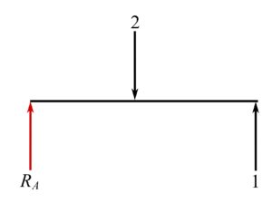
Example 1
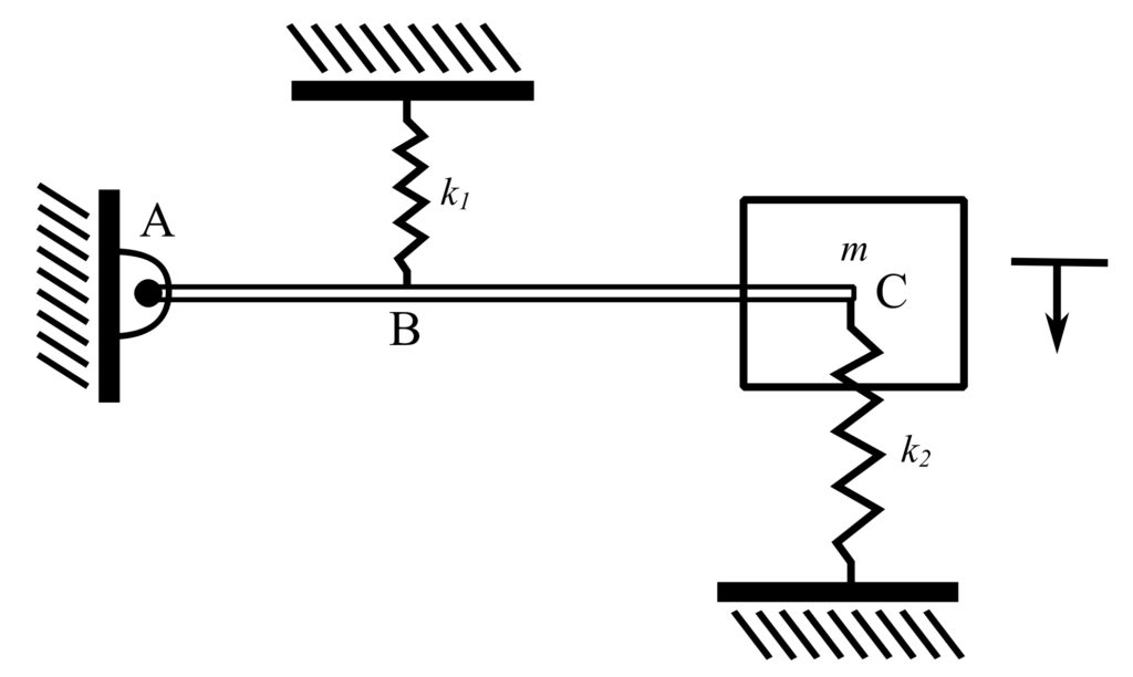
Stiffness
Apply unit deflection to  and calculate the total load.
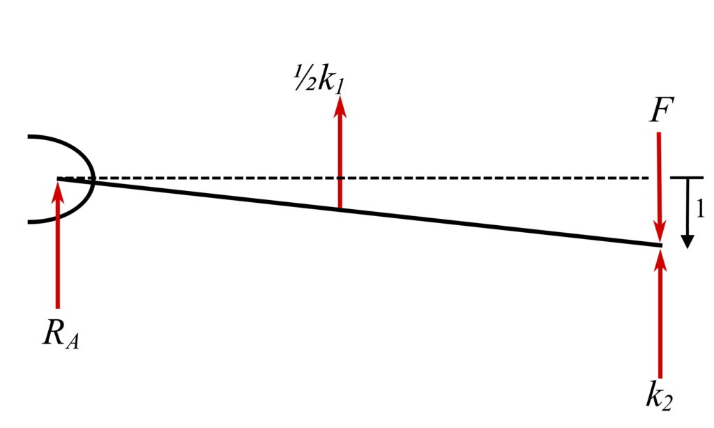
![\[+\circlearrowleft\sum{M_A} = k_1\Big(\frac{1}{2}\Big)\Big(\frac{1}{2}\Big) + k_2(\text{L}) - F(\text{L}) = 0\]](https://engcourses-uofa.ca/wp-content/ql-cache/quicklatex.com-2781841152a68b30fa5a4df7a9d5da1a_l3.png "Rendered by QuickLaTeX.com")
![\[F = \frac{k_1}{4} + k_2\]](https://engcourses-uofa.ca/wp-content/ql-cache/quicklatex.com-d50f9399944c780e748fea05bbb9802e_l3.png "Rendered by QuickLaTeX.com")
Therefore:
![\[k_e = \frac{k_1}{4} + k_2\]](https://engcourses-uofa.ca/wp-content/ql-cache/quicklatex.com-5125eff9900aa10873d3edf5bd65dde4_l3.png "Rendered by QuickLaTeX.com")
If  , then:
![\[k_e = \frac{5}{4}k\]](https://engcourses-uofa.ca/wp-content/ql-cache/quicklatex.com-e1b6479001c2ff7beb4ced2dffc9379c_l3.png "Rendered by QuickLaTeX.com")
Example 2
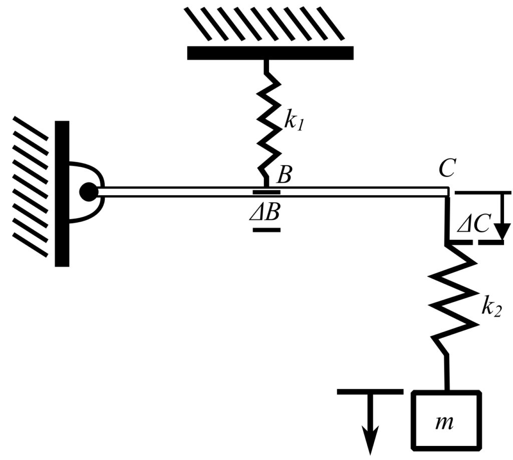
Flexibility
Apply unit load to and calculate the total deflection.
 , therefore:
![\[\Delta_C = \frac{4}{k_1}\]](https://engcourses-uofa.ca/wp-content/ql-cache/quicklatex.com-c259b988a29ffd29c75077236b343cb2_l3.png "Rendered by QuickLaTeX.com")
Therefore :
![\[\begin{split}\Delta \ \text{at} \ M &= \Delta_C + \frac{1}{k_2} \\&= \frac{4}{k_1} + \frac{1}{k_2}\end{split}\]](https://engcourses-uofa.ca/wp-content/ql-cache/quicklatex.com-eaad7219011104269c4ec235dfe809c3_l3.png "Rendered by QuickLaTeX.com")
Thus:
![\[\begin{split}k_\text{eff} &= \frac{1}{\Delta}\\&= \frac{1}{\frac{4}{k_1}+\frac{1}{k_2}}\end{split}\]](https://engcourses-uofa.ca/wp-content/ql-cache/quicklatex.com-839ea7b7b22825732a371a8d15410a91_l3.png "Rendered by QuickLaTeX.com")
If  , then:
![\[k_\text{eff} = \frac{k}{5}\]](https://engcourses-uofa.ca/wp-content/ql-cache/quicklatex.com-6d8919f65c76bf58ec56a468c02c1c27_l3.png "Rendered by QuickLaTeX.com")
Equivalent Spring Constant Equations
1. axial springs in parallel
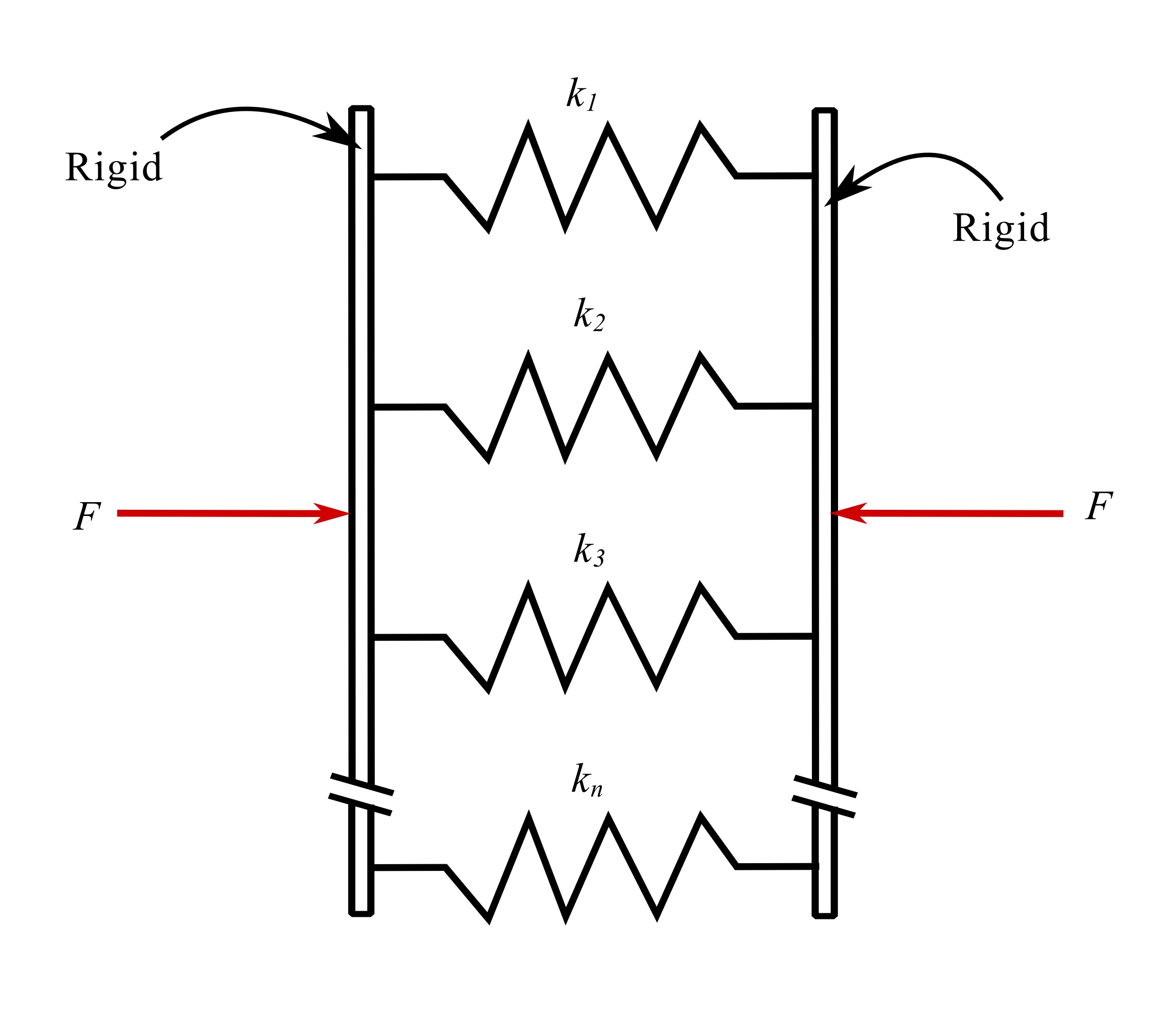
![\[k_e = k_1 + k_2 + k_2 + k_3 + … + k_n\]](https://engcourses-uofa.ca/wp-content/ql-cache/quicklatex.com-1c7548c7d44e4d9ac12f01ce9a9e1617_l3.png "Rendered by QuickLaTeX.com")
2.
axial springs in series
![\[k_e = \frac{1}{\frac{1}{k_1} + \frac{1}{k_2} + … + \frac{1}{k_n}}\]](https://engcourses-uofa.ca/wp-content/ql-cache/quicklatex.com-efbd8bd12f173853fa1e3a28cfa1be2b_l3.png "Rendered by QuickLaTeX.com")
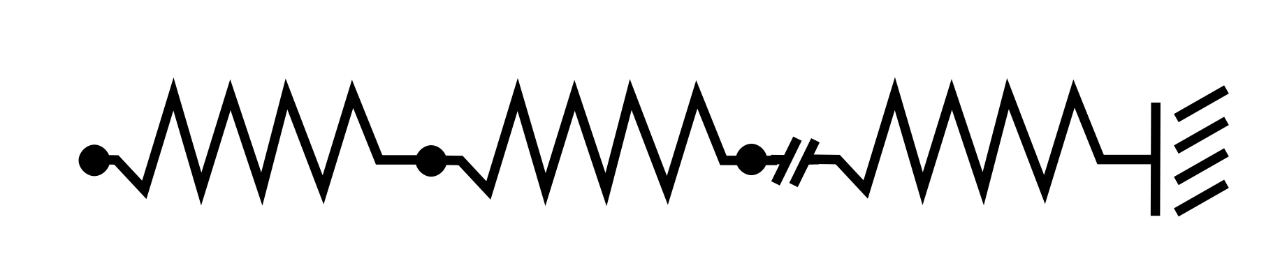
3.Springs in parallel and series
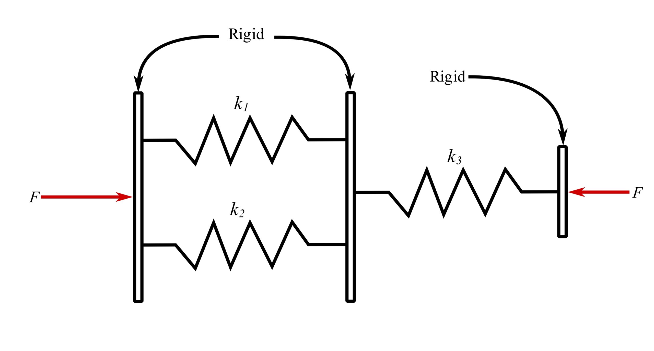
![\[k_e = \frac{k_1k_3 + k_2k_3}{k_1 + k_2 + k_3}\]](https://engcourses-uofa.ca/wp-content/ql-cache/quicklatex.com-1ea7fc10c1880b0d93b3169009c2e103_l3.png "Rendered by QuickLaTeX.com")
4.Inclined axial spring
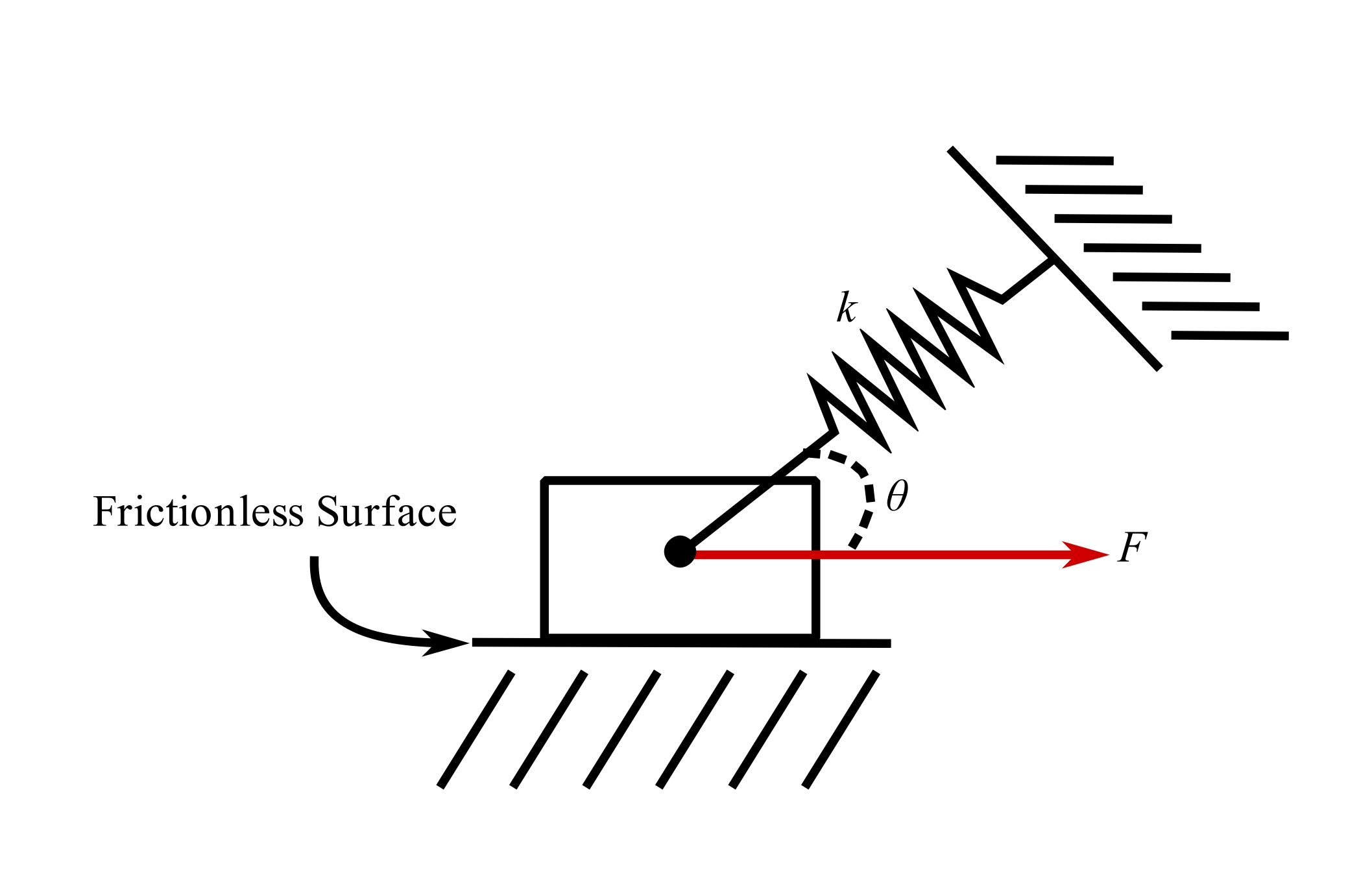
![\[k_e = k\cos^2\theta\]](https://engcourses-uofa.ca/wp-content/ql-cache/quicklatex.com-90cd1d1388226396c99b969d42800531_l3.png "Rendered by QuickLaTeX.com")
5.Rotating bar with spring support
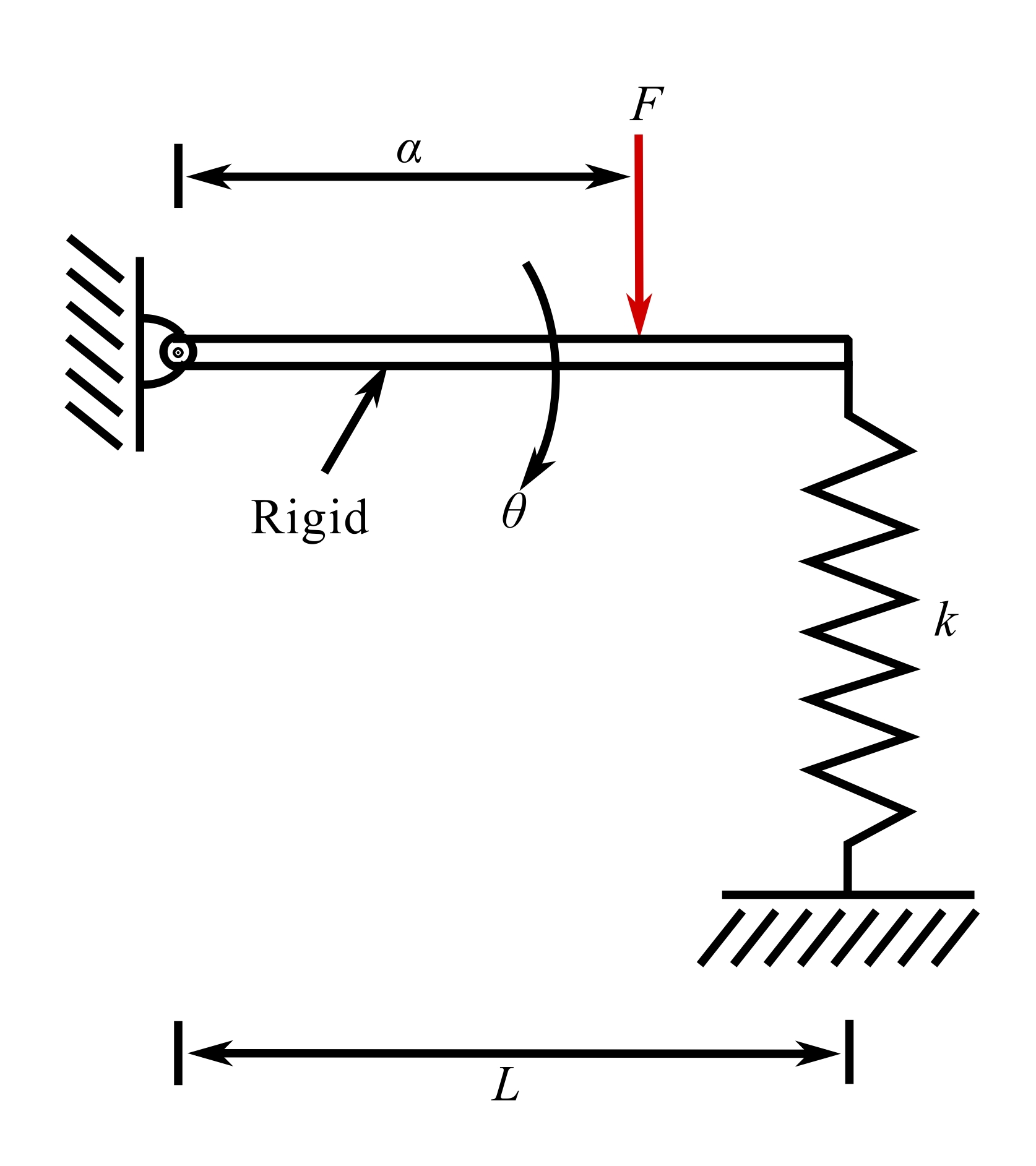
![\[k_e = k\Big(\frac{L}{a}\Big)^2\]](https://engcourses-uofa.ca/wp-content/ql-cache/quicklatex.com-e3932c3102a630dd2f61a1d5abc912c6_l3.png "Rendered by QuickLaTeX.com")
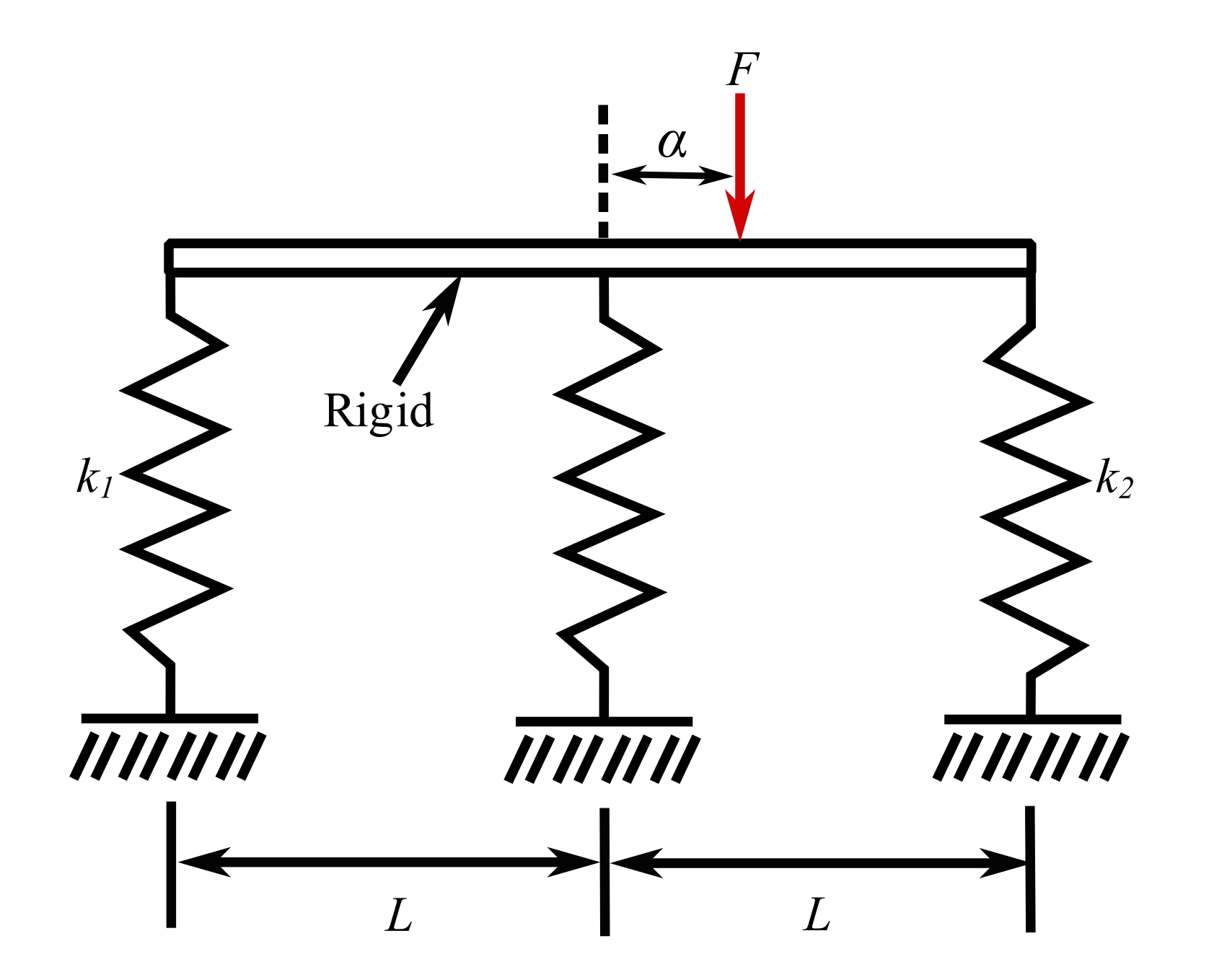
6.Rigid bar supported on two springs
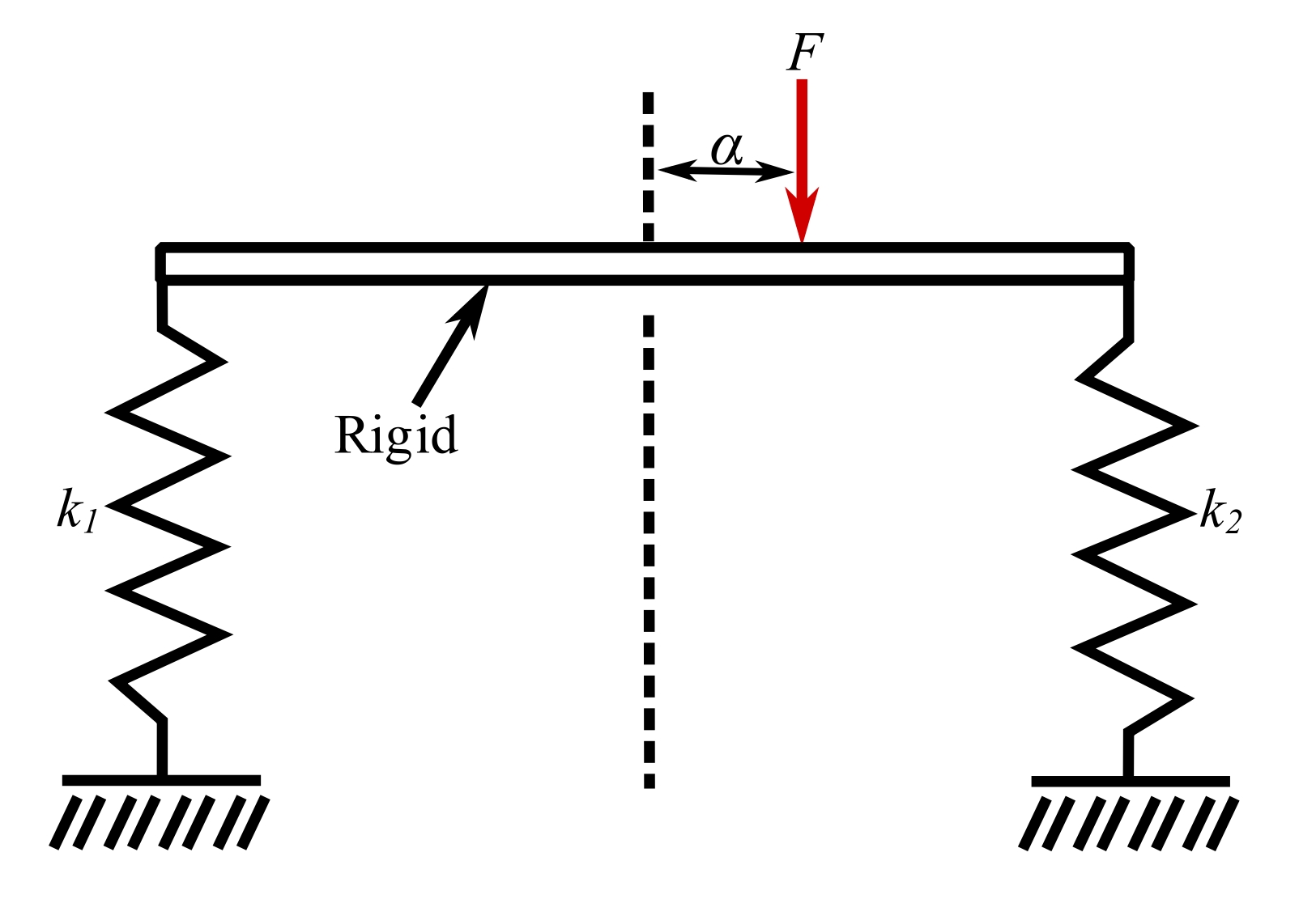
![\[k_e = \frac{4k_1k_2}{k_1[1 + \frac{a}{L}]^2 + k_2[1 + \frac{a}{L}]^2}\]](https://engcourses-uofa.ca/wp-content/ql-cache/quicklatex.com-10e73a1992c883dbfaf5e5ec833d46a4_l3.png "Rendered by QuickLaTeX.com")
7.Rigid bar supported on three springs
![\[k_e = \frac{3k}{1 + \frac{3}{2}(a / L)^2}\]](https://engcourses-uofa.ca/wp-content/ql-cache/quicklatex.com-6990f8d7d82993f4a1a6705b5f299d27_l3.png "Rendered by QuickLaTeX.com")
8.Axially loaded bar
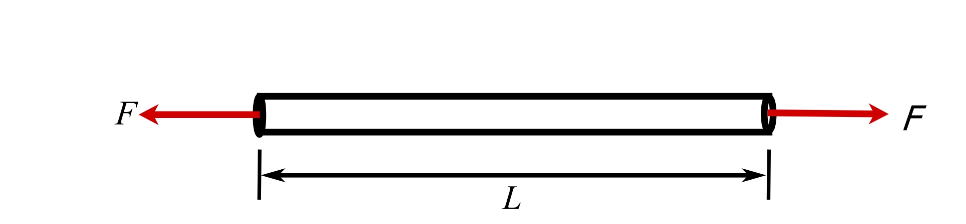
![\[k_e = \frac{AE}{L}\]](https://engcourses-uofa.ca/wp-content/ql-cache/quicklatex.com-85b2fc1e482939fe612291dd2936750c_l3.png "Rendered by QuickLaTeX.com")
Where  is the cross-sectional area, and
  is the elastic modulus.
9.Axially loaded tapered bar
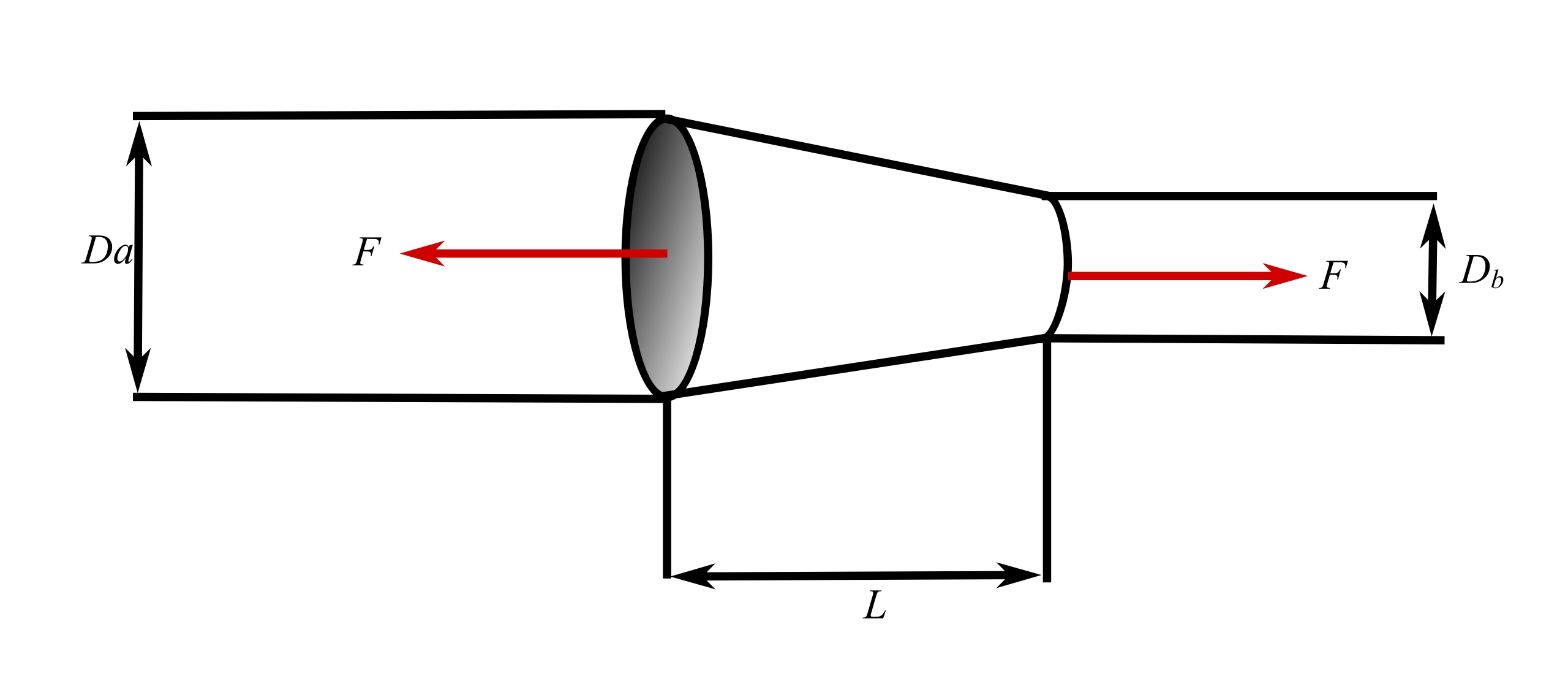
![\[k_e = \frac{\pi E D_a D_b}{4L}\]](https://engcourses-uofa.ca/wp-content/ql-cache/quicklatex.com-f5fb68e2697f25f7060dd05bc4184dff_l3.png "Rendered by QuickLaTeX.com")
10.Axially helical spring
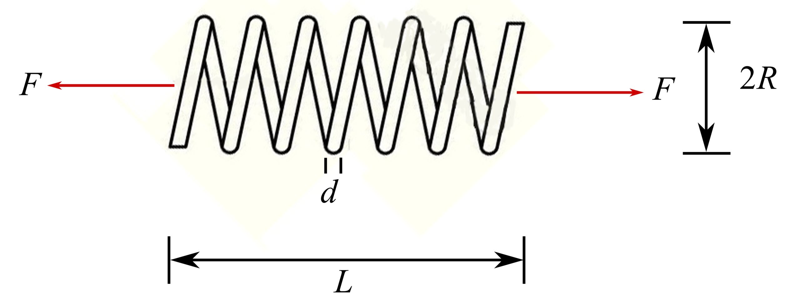
![\[k_e = \frac{Gd^4}{G4nR^3}\]](https://engcourses-uofa.ca/wp-content/ql-cache/quicklatex.com-021575482fc9233bd7ba76dbc4565768_l3.png "Rendered by QuickLaTeX.com")
Where is the active number of turns, and  is the elastic shear modulus.
11.Torsion of a uniform shaft
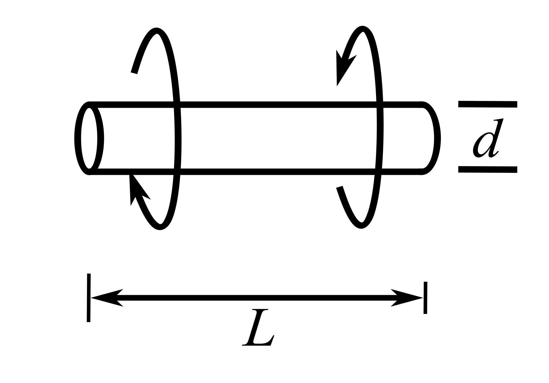
![\[k_e = \frac{GJ}{L}\]](https://engcourses-uofa.ca/wp-content/ql-cache/quicklatex.com-68f952ec718d4c6eb066b14434f255c5_l3.png "Rendered by QuickLaTeX.com")
Where  is the torsional constant of cross section (
 ).
).
12.Torsion of a tapered circular shaft
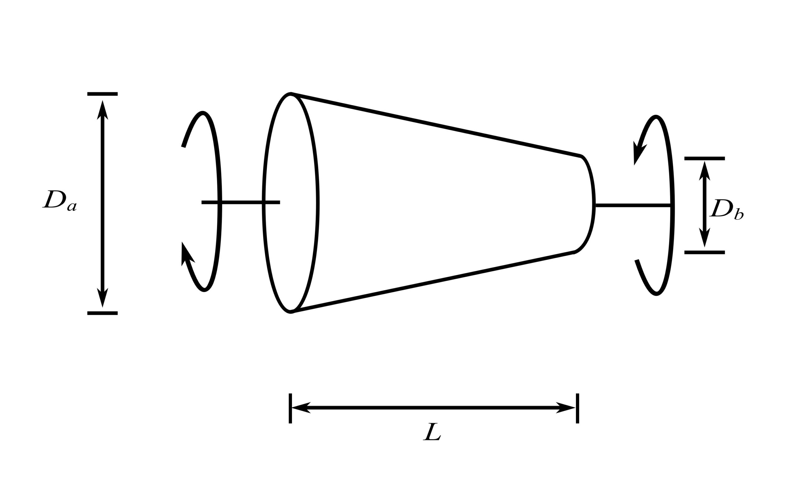
![\[k_e = \frac{3\pi}{32}\frac{D_b^4 G}{L\big[\frac{D_b}{D_a}+(\frac{D_b}{D_a})^2+(\frac{D_b}{D_a})^3\big]}\]](https://engcourses-uofa.ca/wp-content/ql-cache/quicklatex.com-bd447e07082d9185c7ce2c7737a4feea_l3.png "Rendered by QuickLaTeX.com")
13.Spiral torsional spring
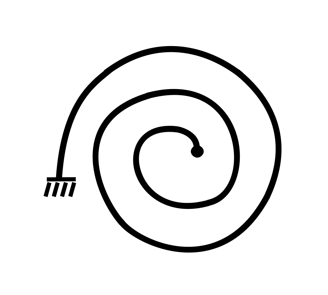
![\[k_e = \frac{EI}{L}\]](https://engcourses-uofa.ca/wp-content/ql-cache/quicklatex.com-1f0dd5571e9ed8c14eeb917372194243_l3.png "Rendered by QuickLaTeX.com")
Where is Young’s modulus.  is the moment of inertia of cross-sectional area, and
  is the total length of the spiral.
14.Cantilever bean, end load
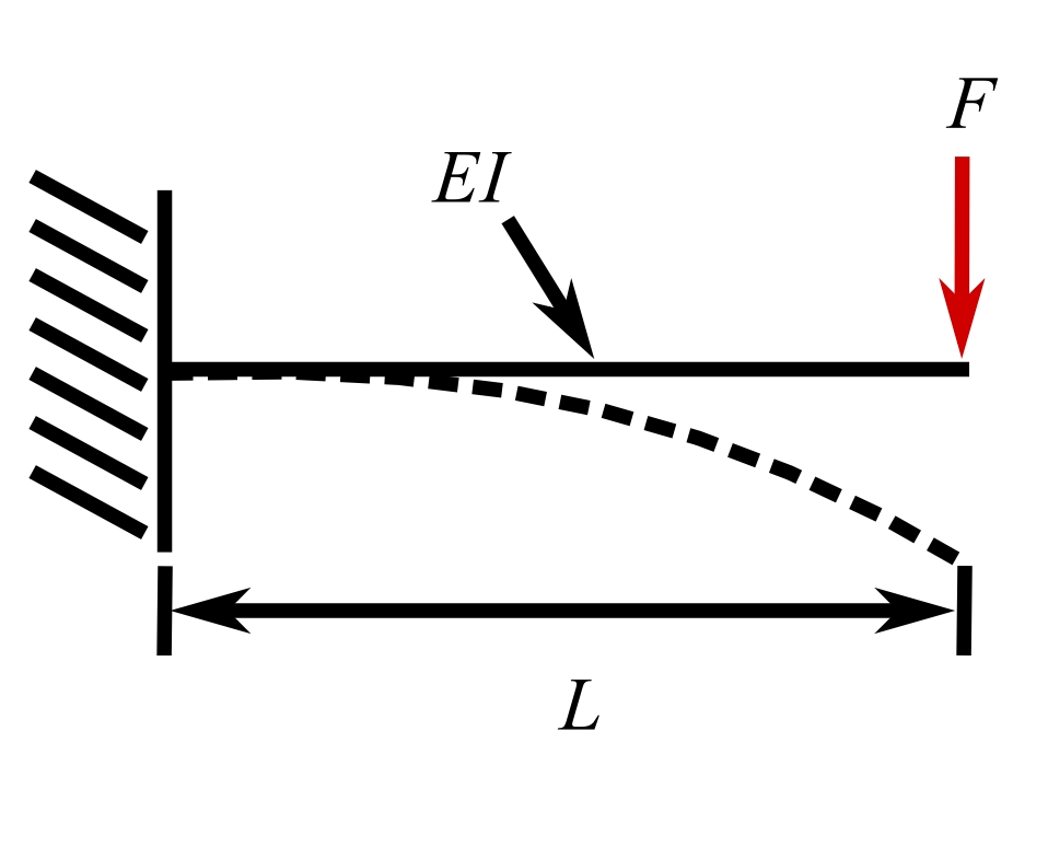
![\[k_e = \frac{3EI}{L^3}\]](https://engcourses-uofa.ca/wp-content/ql-cache/quicklatex.com-8bcffa5868a63ba8c4a8efdbbc766e08_l3.png "Rendered by QuickLaTeX.com")
15.Simply supported bean, load at midspan
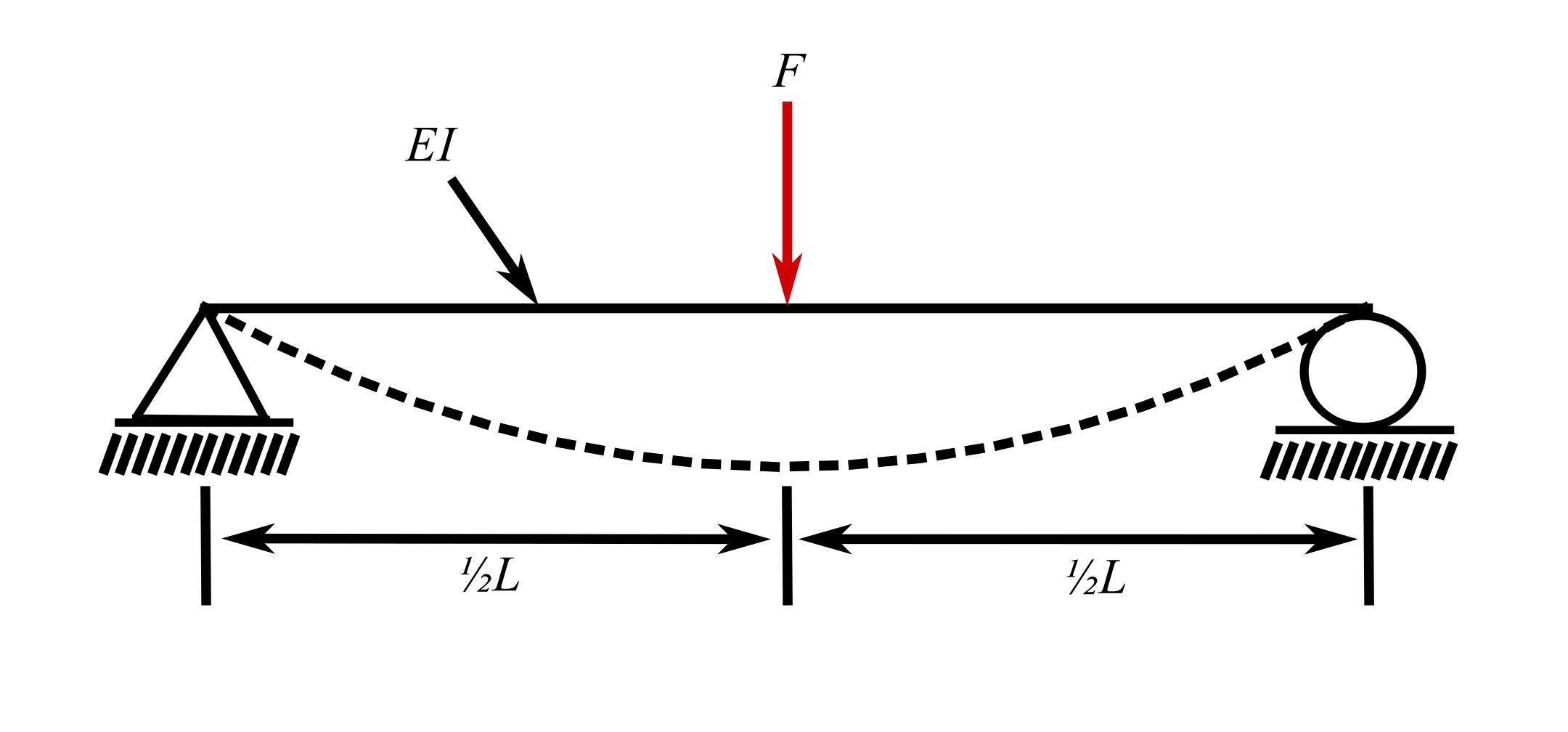
![\[k_e = \frac{48EI}{L^3}\]](https://engcourses-uofa.ca/wp-content/ql-cache/quicklatex.com-721260d04a7e62bca9cacc527d1c571e_l3.png "Rendered by QuickLaTeX.com")
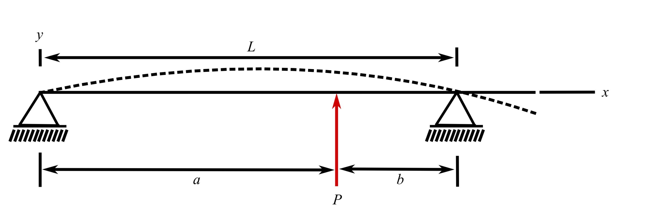
16.Simply supported bean, load anywhere between supports
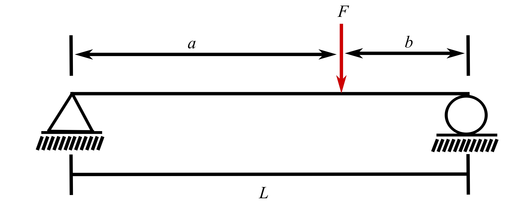
![\[k_e = \frac{3EIL}{a^2b^2}\]](https://engcourses-uofa.ca/wp-content/ql-cache/quicklatex.com-1fece181f7f0ceb879bbd324d8b8557b_l3.png "Rendered by QuickLaTeX.com")
17.Fixed-fixed beam, load at midspan
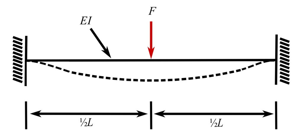
![\[k_e = \frac{192EI}{L^3}\]](https://engcourses-uofa.ca/wp-content/ql-cache/quicklatex.com-87cfd623c7df0025f2c859b9a24b82d4_l3.png "Rendered by QuickLaTeX.com")
18.Fixed-fixed beam, off-center load
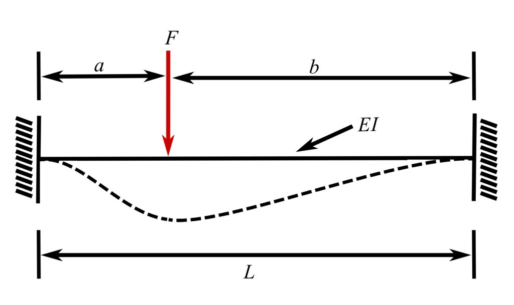
![\[k_e = \frac{3EI(a+b)^3}{a^3b^3}\]](https://engcourses-uofa.ca/wp-content/ql-cache/quicklatex.com-d2dea35ba10a14a1edce290080f5731a_l3.png "Rendered by QuickLaTeX.com")
19.Propped cantilever, load at midspan
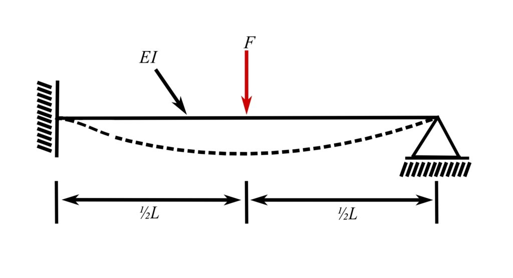
![\[k_e = \frac{768EI}{7L^3}\]](https://engcourses-uofa.ca/wp-content/ql-cache/quicklatex.com-92aaf1492a10f52f38dbbf5061f65788_l3.png "Rendered by QuickLaTeX.com")
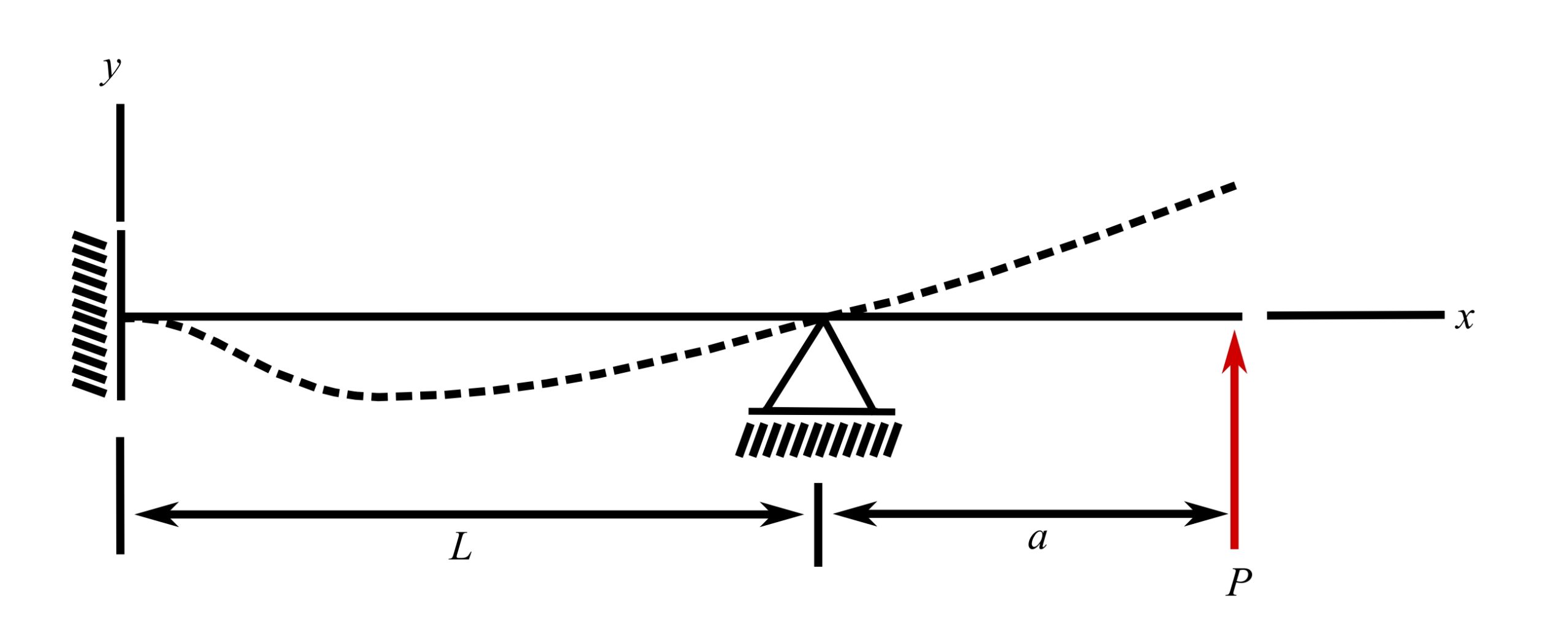
20.Propped cantilever, load at free end
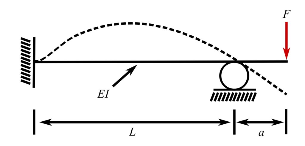
![\[k_e = \frac{24EI}{a^2(3L + 8a)}\]](https://engcourses-uofa.ca/wp-content/ql-cache/quicklatex.com-7649567a2c0d254d2631b3555aaae8cf_l3.png "Rendered by QuickLaTeX.com")
Fixed-fixed beam*
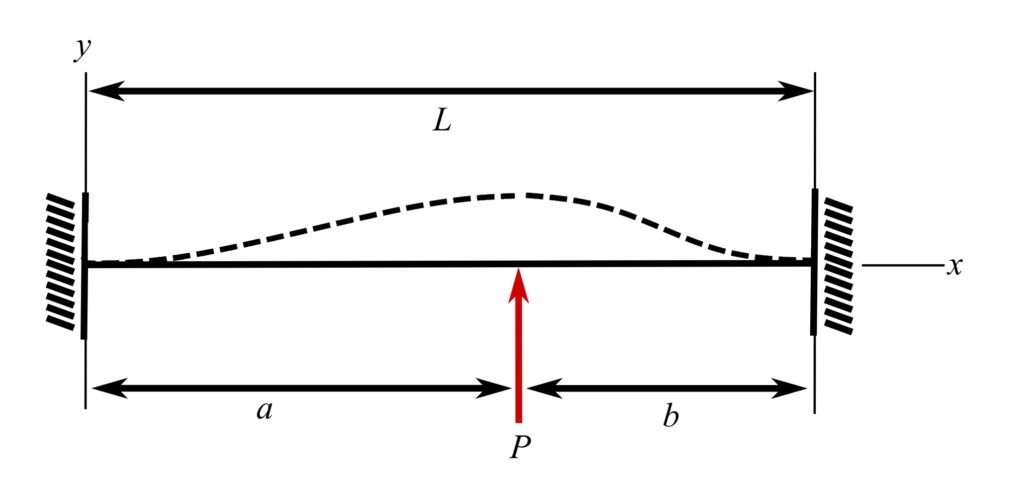
![y = \frac{Pb^2}{6EI\ell^3}\big[(2b-3\ell)x^3 + 3\ell(\ell-b)x^2\big]](https://engcourses-uofa.ca/wp-content/ql-cache/quicklatex.com-d01c44c2783748c8fe512d01be0c7e0e_l3.png "Rendered by QuickLaTeX.com")

![y = \frac{Pb^2}{6EI\ell^3}\big[(2b-3\ell)x^3 + 3\ell(\ell-b)x^2 + \frac{1^3}{b^2}(x-a)^3\big]](https://engcourses-uofa.ca/wp-content/ql-cache/quicklatex.com-05c3326f19e88526bceefcd1d7385087_l3.png "Rendered by QuickLaTeX.com")


Fixed-pinned beam with overhang*
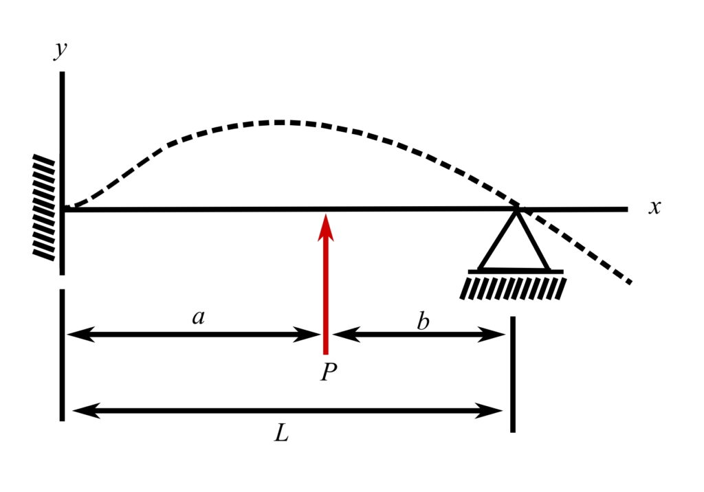
![y = \frac{P}{12EI}\Big[3b\Big(1-\frac{b^2}{\ell^2}\Big)x^2-\frac{b}{\ell}\Big(3-\frac{b^2}{\ell^2}\Big)x^3\Big]](https://engcourses-uofa.ca/wp-content/ql-cache/quicklatex.com-3739dc02d9639ef7d0c279a78173b922_l3.png "Rendered by QuickLaTeX.com")
![y = \frac{P}{12EI}\Big[3b\Big(1-\frac{b^2}{\ell^2}\Big)x^2-\frac{b}{\ell}\Big(3-\frac{b^2}{\ell^2}\Big)x^3 + 2(x-a)^3\Big]](https://engcourses-uofa.ca/wp-content/ql-cache/quicklatex.com-fbbe93899ac183178d6edc35938310d5_l3.png "Rendered by QuickLaTeX.com")


Fixed-pinned beam with overhang (P at x = l + a)*


![y = \frac{Pa}{4EI\ell}\Big[x^3-\ell x^2-\Big(\frac{2\ell}{3a}+1\Big)(x-1)^3\Big]](https://engcourses-uofa.ca/wp-content/ql-cache/quicklatex.com-40ab92d6d12a83445064bb1b81586fd3_l3.png "Rendered by QuickLaTeX.com")

Pinned-pinned beam with overhang*

Pinned-pinned beam with overhang (P at x = l + a)*
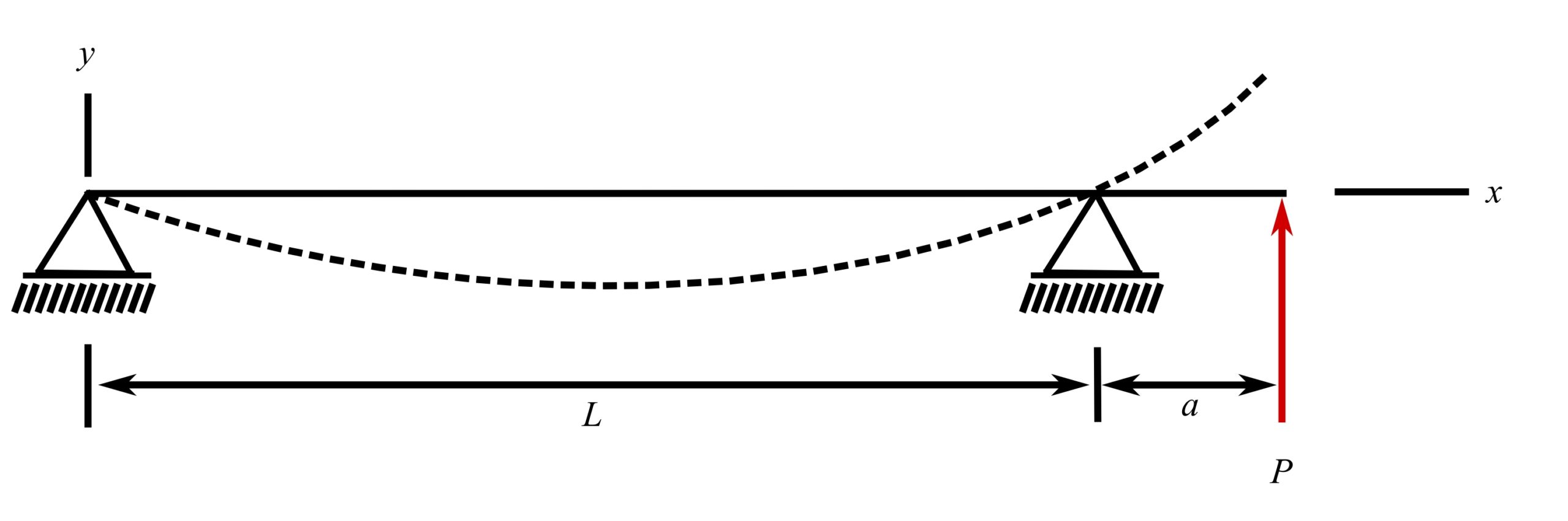

![y = \frac{P}{6EI\ell}\big[ax(x^2-\ell^2)-(\ell+a)(x-\ell)^3\big]](https://engcourses-uofa.ca/wp-content/ql-cache/quicklatex.com-4d371160f35e9cec5ab1a4d6aadb57db_l3.png "Rendered by QuickLaTeX.com")

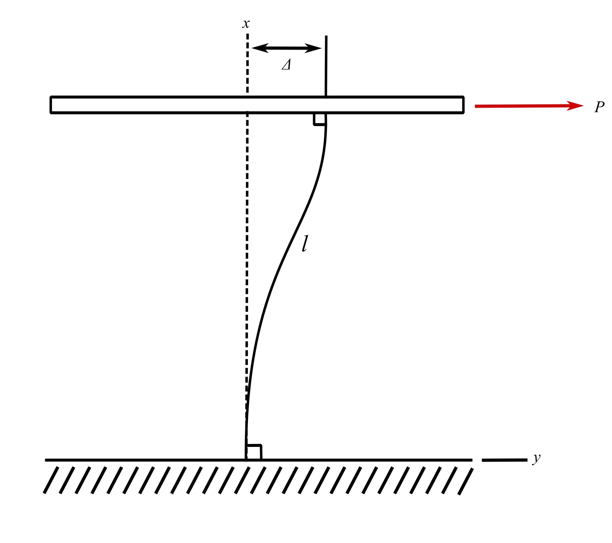
Fixed-fixed beam with lateral displacement


* Axial extensions due to axial end constraints considered negligible
Torsional Oscillations
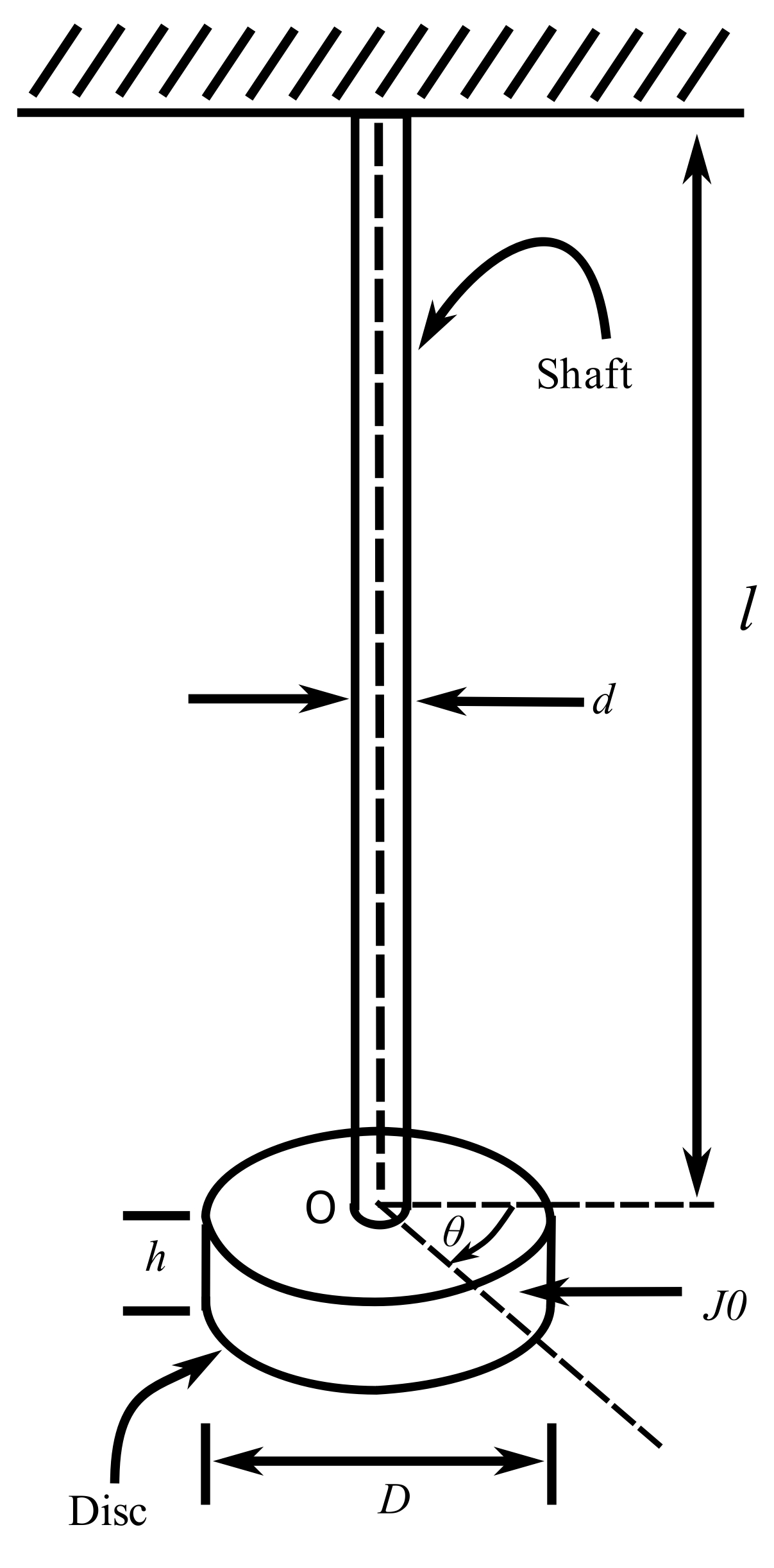
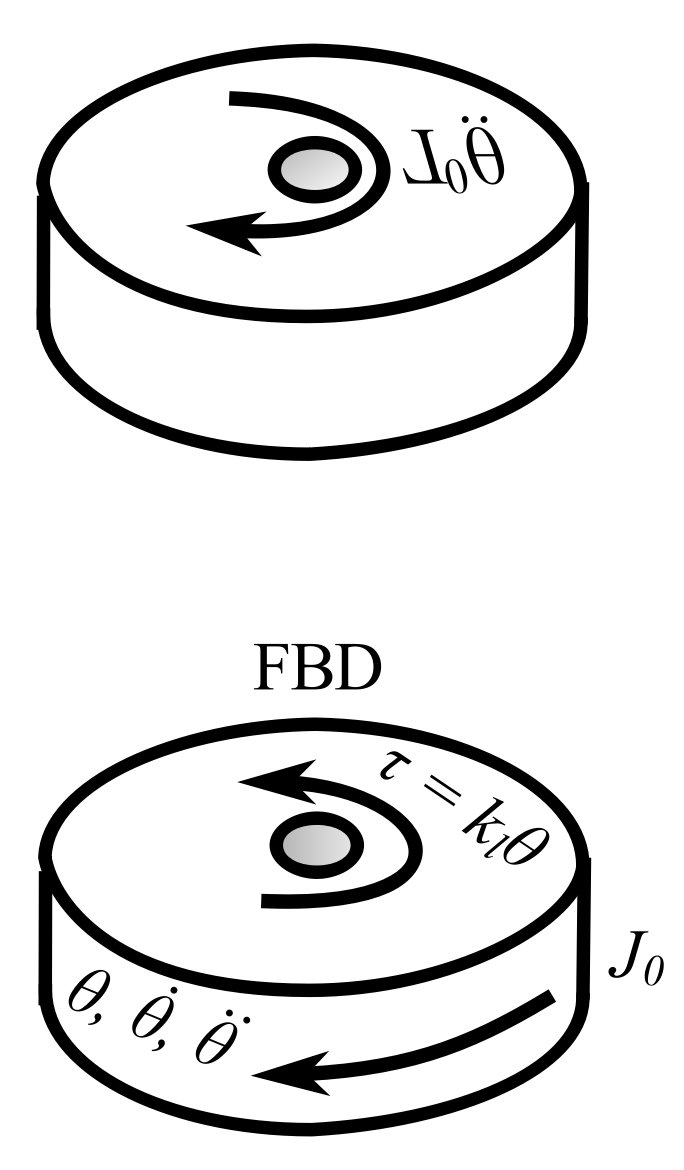
![\[\begin{split}+\circlearrowright \sum{M_o} &= J_o\ddot{\theta} \\&= -\hat{k}\theta\end{split}\]](https://engcourses-uofa.ca/wp-content/ql-cache/quicklatex.com-1b5dfe45b50e3c44c30e538fc2e2c853_l3.png "Rendered by QuickLaTeX.com")
![\[J\ddot{\theta} + \hat{k}\theta = 0\]](https://engcourses-uofa.ca/wp-content/ql-cache/quicklatex.com-6f30fec6d83a1be8f6ae0812d0d13223_l3.png "Rendered by QuickLaTeX.com")
Let  . From the strength of the material:
![\[\tau = \mu \alpha I\]](https://engcourses-uofa.ca/wp-content/ql-cache/quicklatex.com-a3cb0b3966618243238a9af86a6b6a04_l3.png "Rendered by QuickLaTeX.com")
Where  is the modulus of rigidity,
  is the angle of twist/unit length and is the polar second moment of inertia. Therefore:
![\[\tau = \mu \frac{\theta}{\ell}I = \hat{k}\theta\]](https://engcourses-uofa.ca/wp-content/ql-cache/quicklatex.com-e9053b31f6cacaa06bfe90b2983fadaa_l3.png "Rendered by QuickLaTeX.com")
![\[\hat{k} = \frac{\mu I}{\ell}\]](https://engcourses-uofa.ca/wp-content/ql-cache/quicklatex.com-e864df28be7c1aebcb3e8bfa3963fb34_l3.png "Rendered by QuickLaTeX.com")
For soild circular cross sections:
![\[I = \frac{\pi d^4}{32}\]](https://engcourses-uofa.ca/wp-content/ql-cache/quicklatex.com-7609519ea81d2b51a7a78adfd711e7d1_l3.png "Rendered by QuickLaTeX.com")