Biomechanics and Bioengineering of Orthopaedics: Tension as a failure mode
This section provides an introduction to the biomechanics of surgical screws and suture anchors.
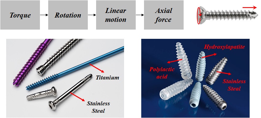
A screw is a simple machine that converts torque into an axial force (Fig. 2-1). A surgical screw is made of metals such as stainless steel or titanium, or a biodegradable material.
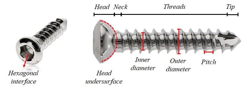
The screw includes four parts: head, neck, threads, and tip (Fig. 2-2). The head provides the connection for the screwdriver and prevents the screw from advancing into the material. The interface between the screwdriver and the head is usually hexagonal. The undersurface of the head is usually hemispherical to increase the surface area for load transfer. The diameter of the shaft is called the core or inner diameter. The outer diameter determines the minimum diameter of the hole, through which the screw could slide, without engagement of threads. Pitch is the linear distance a screw travels for each complete turn.
Classification of surgical screws
There are different ways to classify surgical screws (Fig. 2-3).
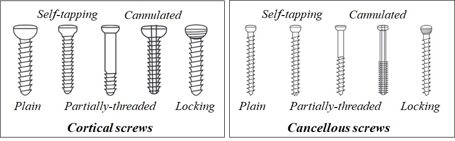
A cortical screw is designed to engage in cortices, while, a cancellous screw gains purchase in the cancellous bone. A screw could be threaded along its total length or partially.
A self-tapping screw has a cutting flute at the tip, which cuts a channel into the bone for threads.
A standard screw has a solid central core, while a cannulated screw has a canal drilled through the core, which could be used to guide the screw over a guide wire.
In a locking screw, the head is also threaded. This type is used to fix a locking plate, which has reciprocal grooves around the plate holes.
Lag screw is a technique that provides interfragmentary compression across a fracture line (Fig. 2-4). The principle of lag screw, states that, the threads must only engage in the far part to compress the fragments. A lag screw is inserted perpendicular to the fracture line.
To insert a fully-threaded screw as lag screw, the near fragment is drilled with diameter higher than the outer diameter, so that, the threads gain no engagement with the bone in this portion. For the far fragment, the hole is drilled with the same diameter as the inner diameter, and after tapping, the threads gain purchase inside this portion.
After insertion of a lag screw, three pairs of forces are acting inside the system. The compression between the screw head and the near fragment. The interfragmentary compression between the near and far fragments, and the shearing force between the threads and the far fragment.
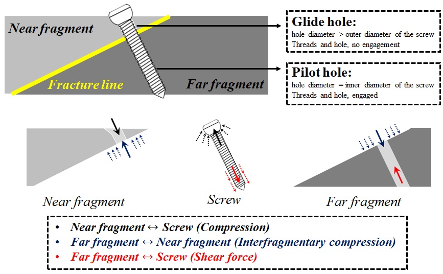
For example, the near fragment is subjected to a load, downward, due to the pressure from the screw head, and an upward load, due to contact with the far fragment.
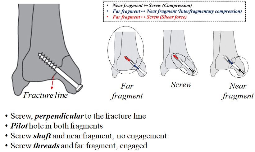
For a partially-threaded screw, the lagging technique could be applied directly (Fig. 2-5). For this type of screw, a hole with the same diameter as the inner diameter of the screw is drilled in both fragments. Since the screw inside the near fragment does not have threads, the screw does not engage with the bone in this part. For a partially threaded screw as a lag screw, the threads are only located in the far fragment. The pair of forces acting on the partially-threaded screw are similar to those in the fully-threaded lag screw.
Pullout strength of a bone-screw construct
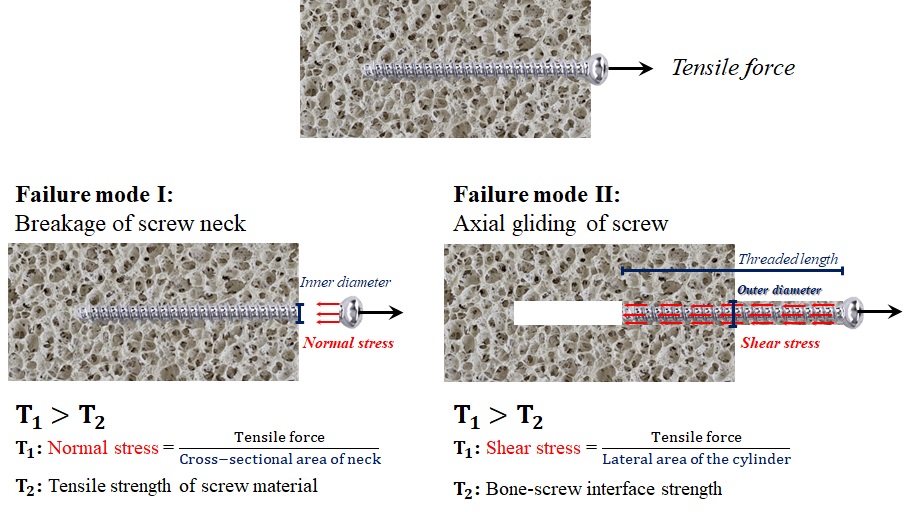
Pull-out strength of a bone-screw construct is defined as the maximum tensile force the structure could tolerate before failure (Fig. 2-6).
The common modes of failure of a screw, subjected to tensile force, are the neck breakage, and gliding alongside the axial axis.
In the first mode, the normal stress within the neck, become greater than the tensile strength of the material, used in the screw. The neck has the least diameter inside the screw body, and therefore, the normal stress at this location, is greater than those at any other portion of the screw. In the second mode, the shear stress on the lateral threaded side, exceeds the bone-screw interface strength.
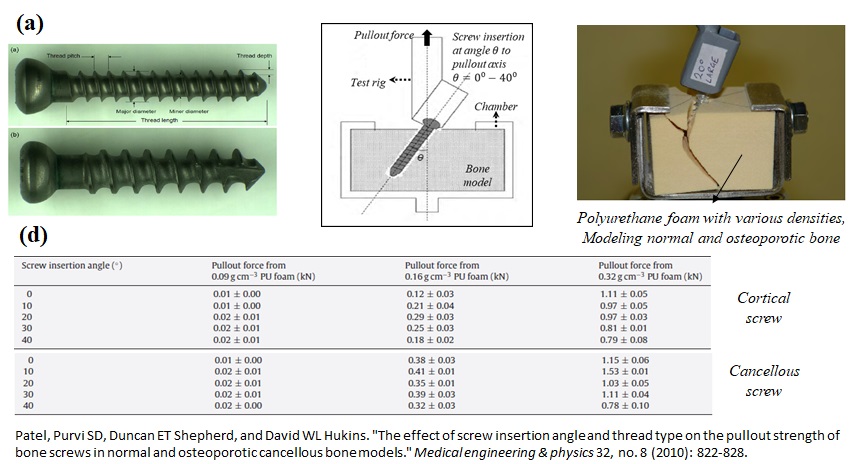
Researchers have conducted experimental and computational studies on how different parameters affect the pullout strength of the bone-screw constructs (Fig. 2-7). In a study performed by Patel and her colleagues, the effects of screw insertion angle, thread type, and bone quality were investigated. In this work, the pullout strength was determined for two types of titanium screws, at varying angles between zero and forty degrees.
For modeling the normal and osteoporotic bones, three types of polyurethane foam with various densities were utilized. In the test set, an axial displacement with a constant rate was applied to the screw and the associated axial forces were recorded. The maximum value of axial force was reported as the pullout strength. The study showed that:
- Pullout strength significantly increased with increasing PU foam density.
- For screws placed axially, and sometimes at ten degrees, the second failure mode discussed earlier, happened.
- For screws inserted at ten to forty degrees, the PU foam material above the screw was crushed at the failure point.
suture-anchor construct
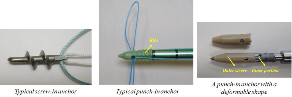
A suture-anchor construct holds an injured tissue close to the bone, until the final stage of tissue remodeling (Fig. 2-8). The anchor fixes the sutures to the bone. Anchors are generally classified as screw-in and non-screw-in (punch-in) types (Fig. 2-8).
In screw-in anchors, the threads achieve purchase in the subcortical bone. Non-screw-in anchors are pushed into the bone and might change their morphology after insertion to increase the pull-out strength.
A typical punch-in anchor is inserted into the bone through press-fit, and after insertion, the ribs of the anchor resist pull-out by friction. In this design of punch-in anchor, the inner part is forced inside the outer sleeve to increase the pull-out strength.
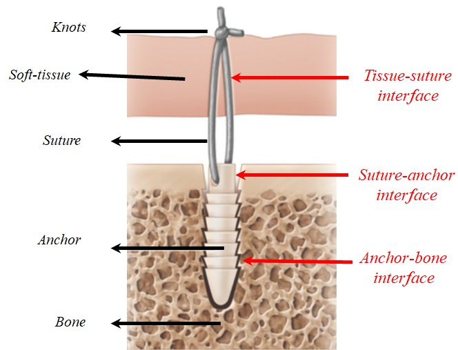
A suture-anchor construct could fail at the interfaces between the tissue, suture, anchor, and bone (Fig. 2-9). All components of a construct must work together to achieve a sufficient level of pull-out strength.
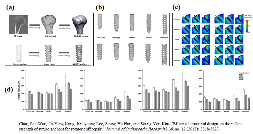
In a computational study (Fig. 2-10), Chae and his colleagues recently simulated the pullout strength of suture anchors. They firstly converted the computed tomography scans of five cadaveric humeri into three-dimensional models for the cortical and cancellous bone, and cartilage. In addition, three-dimensional models were constructed for 5 types of suture anchors with different thread designs in two sizes. The suture anchors were embedded into the bone models and a constant displacement rate was applied in three directions. The pullout strength was calculated as the maximum tensile force.
The results showed that the Healiccoil design has higher pull-out strength, compared with other thread designs. In this study, the osteoporotic bone was modeled by degrading the mechanical properties, used for the cortical and cancellous bone.