Biomechanics and Bioengineering of Orthopaedics: Bending as a failure mode
This section provides an introduction to mechanics of bending, internal and external fixators.
Mechanics of Bending
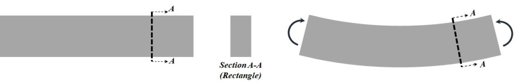
Consider a bar with a rectangular cross-section (Fig. 4-1). When moments are applied at the end of the bar, the bar bends. A bending bar is called beam.
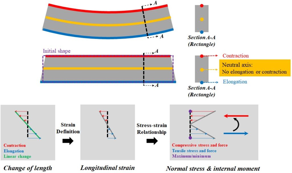
If we isolate imaginary fibres at the top, middle, and bottom of the beam (Fig. 4-2), and make these fibres straight, we could see that the fibre at the top, shrinks, while the fibre at the bottom, elongates. For the middle fibre, the length remains unchanged, and no contraction or elongation is observed. This fibre defines the neutral axis of the beam (Fig. 4-2).
A simple theory for beams, assumes that, the change of length is linear within the beam height (Fig. 4-2). If the change of length is normalized, with respect to the initial length, the longitudinal strain is obtained. And, if the strain is multiplied by Young’s modulus, which was a material property, the normal stress is found. Normal stress is equal to zero at the neutral axis, and changes linearly, based on the distance from the axis. The points at the top and bottom of the beam, have extreme stress values (Fig. 4-2). These points reach the strength of the material sooner than any other point in the beam, and the failure starts from these points. The normal stresses, above and below the neutral axis, build a couple, which is equal to the external moment.
Bending stiffness
The bending stiffness depends on the material used in the beam, and the distribution of material within the cross-section. A structure made of material with higher Young’s modulus, is more difficult to bend, and has higher bending stiffness.
The material distribution within the cross-section is another important factor, affecting the bending stiffness. Consider an example in which, the same ruler bends in two different directions (Fig. 4-3). For the first case, the beam height is small, and to tolerate the applied moment, higher stresses and strains are induced in the bar. In comparison, for the second case, the beam height is considerably larger, and since the lever arm between the compressive and tensile forces increases, much smaller stresses are required to resist the moment. To build beams with higher resistance to bending, it is important to put more material far from the neutral axis. In mechanics, the material distribution within the cross-section of a beam is described as the moment of inertia. A beam with a higher moment of inertia has a higher resistance to bending.
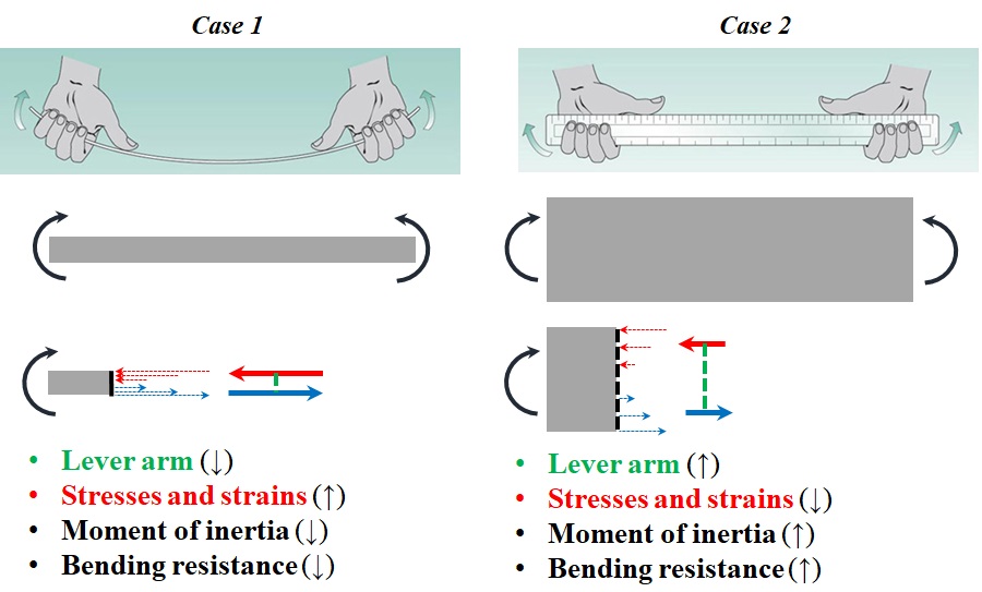
Plate Fixation
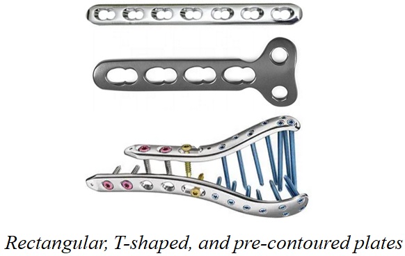
Plates are the most common fracture fixation devices. A plate is a sheet of metal that is used to fasten pieces of bone together, and acts like a beam. Specifications of a plate are: 1- regular or pre-contoured 2- Hole design and 3-Working lengths.
Plates are available in various sizes and designs (Fig. 4-4). Plates are usually rectangular. They could also be T or L shaped or pre-contoured for a specific bone.
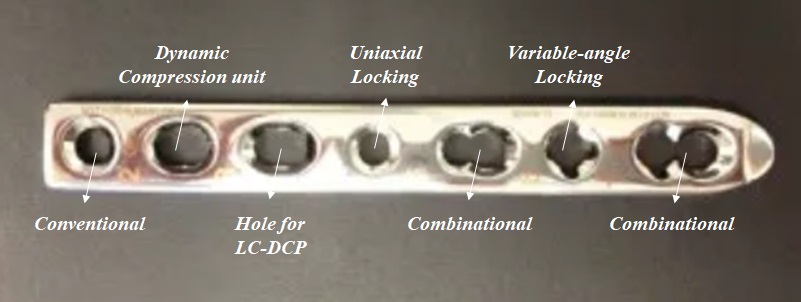
The shape of the screw holes in a plate is referred to as the plate hole design. A variety of plate hole designs are available and used for different functions (Fig. 4-5).
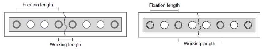
The working length of a plate is defined as the distance between the closest screws at the opposite sides of the fracture (Fig. 4-6).
Stiffness of bone-plate construct
The stiffness of a bone-plate construct, depends on many factors.
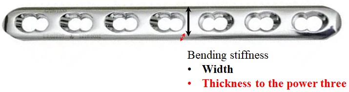
For a regular plate, the plate thickness and width affect the bending stiffness, and therefore, the overall stiffness of the construct. The construct stiffness also increases with the number of screws used to stabilize the bone fragments (Fig. 4-7).
The working distance is another important factor. When the distance between the closest screws at the opposite sides of the fracture is small, the construct shows higher stiffness.
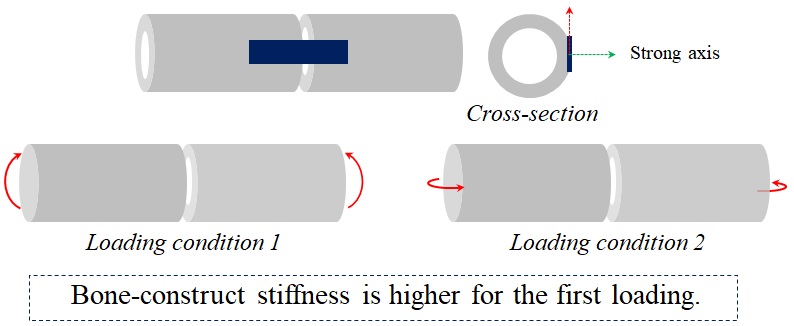
The loading condition also affects the stiffness. The construct, shown in Fig. 4-8, have a higher stiffness when the first loading condition is applied. For the first case, the plate bends with respect to its strong axis, with a considerably higher moment of inertia. while for the second case, the bending occurs with respect to the weak axis and the stiffness of the complex drastically decreases.
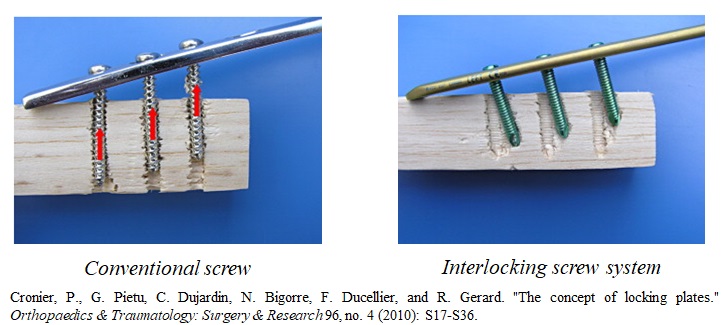
The hole design also affects the way load is transferred within the construct and its stiffness. The conventional plate relies on friction between bone and plate, while in a locking plate, the screws and the plate together form a fixed device, which is much more stable in carrying loads (Fig. 4-9).
A plate is used in a number of different mechanical functions, based on the location and pattern of fracture and the type of stability required.
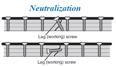
A neutralization plate protects the lag screw from failure under bending and torsion, when the lag screw provides inter-fragmentary compression (Fig. 4-10). A neutralization plate is also called protection plate. A lag screw could be inserted independently, or through the plate hole.
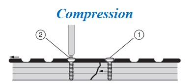
A compression plate produces compression across a fracture (Fig. 4-11). To achieve this functionality, the first screw is installed in a neutral position, in a plate hole on one side of the fracture. Then, the second screw is inserted in an eccentric position in a plate hole on the other side, which pulls the fragments together, producing inter-fragmentary compression.
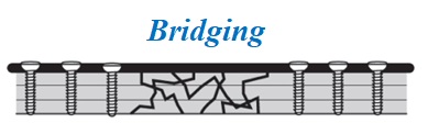
A bridging plate is applied across a comminuted fracture and stabilizes the bone at the fracture span (Fig. 4-12). The bridging plate provides a splint for the fracture, with the correct alignment, when bone is healing. Due to bone loss or poor bone quality in comminuted fractures, the bridging plate solely tolerates the applied load, and is in danger of failure, unless early healing occurs alongside the far cortex.
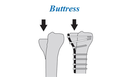
A buttress plate is a supporting plate for fractures at metaphysis (Fig. 4-13). The types of plate usually contour the metaphyseal portion, are anchored firmly to the diaphysis, and prevent fragments from sliding.
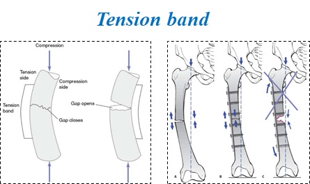
A tension band plate is used for long fractured bones under eccentric loads (Fig. 4-14). For a bone under eccentric loads, one side of the cortex is under compression, and the other side, under tension. A tension band is installed on the tensile side of the bone, tolerate the tension, allowing the bone to carry only the compression.
External fixators
External fixators stabilize fractures using an external frame. There are two types of external fixators, the pin-to-bar fixators, and the ring fixators. They could also be combined in a hybrid system.
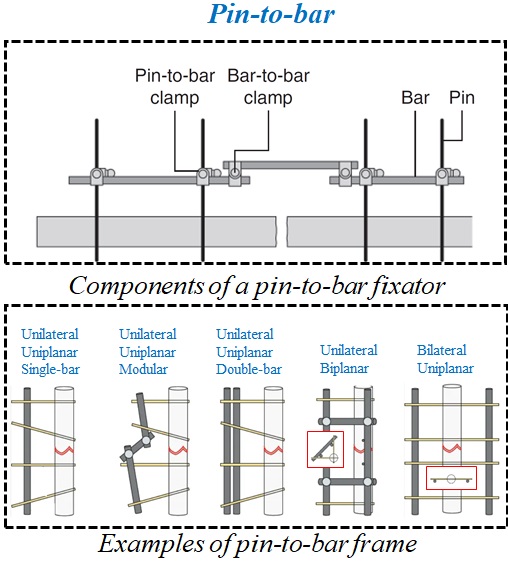
In a pin-to-bar fixator (Fig. 4-15), the bars are inserted into the bone fragments, and then, they are connected to an external frame by clamps. The pin-to-bar fixators could be unilateral or bilateral. In a unilateral fixator, the frame covers less than 90 degrees around the bone, while for bilateral fixators, the frame coverage is more than 90 degrees. The pins of an external fixator could all lie in a single plane, in which case, the fixator is called uniplanar, or could be oriented in different directions.
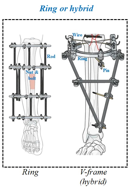
A ring fixator is used in more complex situations, such as fracture mal-union or limb deformity correction (Fig. 4-16). In a ring system, the pre-tensioned wires fix the fracture fragments, and the external ring supports the wires. The rings, themselves, are connected by rods, using nuts and bolts.
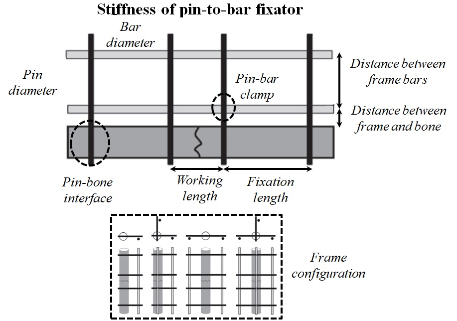
The stiffness of a pin-to-bar fixator depends on many factors (Fig. 4-17):
- The bending stiffness of the bars and pins affects the system’s stiffness largely.
- The bending stiffness of a pin or bar is proportional to its diameter to the fourth power.
- The thread design of the pins determines their purchase inside the bone and affects the overall stiffness of the system.
- The working and fixation lengths are another two important factors. A system with a shorter working length and longer fixation length shows higher stiffness.
- Having the frame components closer to the bone also increases the stiffness of the system.
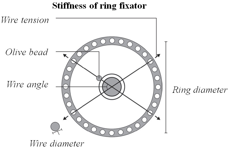
The stiffness of a ring fixator is adjustable by many factors (Fig. 4-18):
- The construct stiffness increases with the wire tension. Depending on the location of the fracture, varying amounts of tension are applied to the wires.
- In stopper wires, a bead is used to contact and control a bone segment.
- The stopper wires provide higher stiffness for the construct.
- The wire angles influence the stiffness in different directions.
- A wire with a larger diameter has higher bending stiffness, which in turn, affects the stiffness of the construct.
- The ring diameter affects the construct stiffness inversely.
- A ring with a smaller diameter leads to a stiffer construct.