Biomechanics and Bioengineering of Orthopaedics: Dimensionless quantities
Material & Structural Behaviour
- Engineering Mechanics
- Force and Moment
- Stress and Strain
- Material Behaviour
- Structural Behaviour
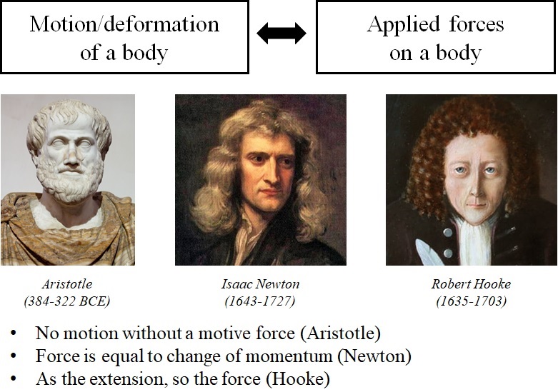
Mechanics is the oldest branch of physics, which is concerned with describing motion and deformation of a body when some forces are applied to it (Fig. 1-1).
The first writing about mechanics dates back to the time of ancient Greeks. Aristotle described the first principle for a stationary body, that there can be no movement without a motive force. Newton states three rules connecting the motion of a body and applied forces. His second rule of motion is the most important principle in classical physics, which states the net applied force to a body is equal to change of momentum. Robert Hooke established the first law of elasticity, that the extension of a spring is proportional to the tension applied to it.
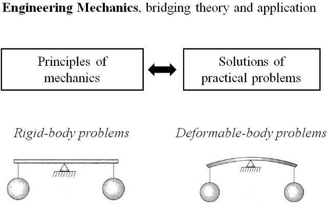
Engineering mechanics is the science of implementing mechanical principles to solve practical problems (Fig.1-2). It links theory to application. Two common types of problems in engineering mechanics are the ones dealing with rigid and deformable solid bodies. In a rigid-body problem, we simply assume that the involved objects could only translate and rotate, without any change in form. While, in a deformable-body problem, the involved objects could also deform.
Force and Moment
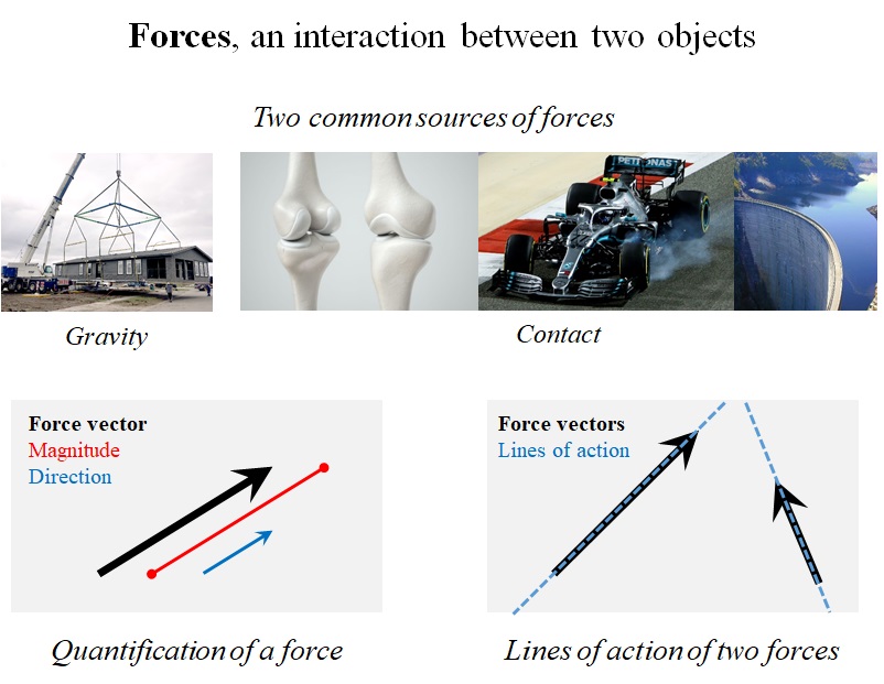
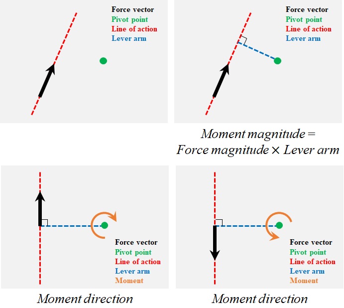
Forces are an interaction between two objects (Fig. 1-3). They come in pair. Gravity and contact are two common sources of forces. Force is a quantity with magnitude as well as direction, and therefore, it is a vector. A force vector could be visualized by an arrow (Fig. 1-3). The length of the arrow is equal to the force magnitude. The line of action of a force is collinear with the force vector. Only in rigid-body problems, forces are allowed to slide along their lines of action.
Addition and multiplication are two basic operations on forces. In order to add two force vectors, Firstly, one of the vectors is translated, such that, its starting point coincides with the end of the other vector. Then, the addition is defined as a vector from the start of the first vector to the end of the second one (Fig. 1-4).

To analyze forces, the vectors are decomposed into components, parallel to the axes of a coordinate system (Fig. 1-5). The selection of the coordinate system is arbitrary, but after selection, we should stick to the system in our computations.

Moment is the tendency created by a force to rotate or twist a body around a point. Our routine life is full of experiences in which a force is applied to an object to rotate or twist it. Similar to force, moment is also a vector.

To find the magnitude of a moment created by a force with respect to a point, called the pivot point, the line of action of the force is drawn first (Fig. 1-7). The lever arm is then defined as the perpendicular distance between the pivot point and the line (Fig. 1-7). The magnitude of the moment is equal to the lever arm multiplied by the force magnitude (Fig. 1-7).
The lever arm, and the line of action of the force construct a plane. The moment is normal to this plane. For two-dimensional problems, the moment is normal to the 2D space, and could be clockwise or counterclockwise, depending on the direction of the force (Fig. 1-7).
Stress and Strain
Stress and strain are two fundamental quantities in mechanics of deformable bodies. Stress is force, normalized with respect to cross-sectional area. Strain is change of length, normalized with respect to the original length. These two quantities are defined for the points within the body, and therefore, could be considered dimensionless.
As an example, consider a circular bar under a tensile force (Fig. 1-8). If an imaginary plane cuts the bar into two parts, we could see that the internal force must have the same magnitude as the tensile force, and opposite direction, in order to satisfy the equilibrium. The internal force comes from a uniform distributed force over the cutting plane. This distributed internal force is called stress, and is equal to the internal force divided by the cross-sectional area.
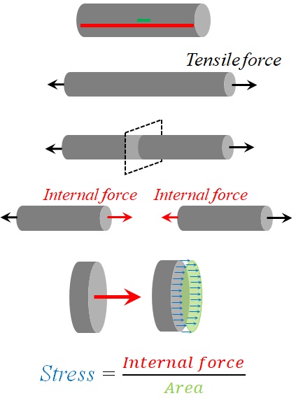
Now, let’s color two line segment on the circular bar, before applying the tensile force (Fig. 1-9). The red line segment extends from the start to the end of the bar, and the green line segment has unit length. After applying the force, the change of length in the red line segment shows the total elongation of the bar; while the change of length in the green line segment is called strain.

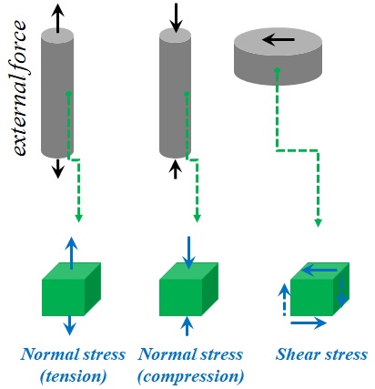
In the current example, the stress was normal to cutting plane. This type of stress is called normal stress. In addition, stress could be tangential to the cutting plane, in which case, we are dealing with the shear stress (Fig. 1-10). Also, normal stress could be tensile or compressive.
Stress-Strain Diagram: Characterization of Material Behaviour
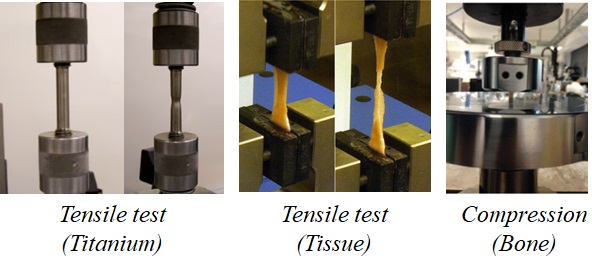
For a specific material, the relationship between stress and strain is obtained from experiment (Fig. 1-11). In an experimental test, a specimen of the material is subjected to a simple mechanical condition, such as tension or compression.
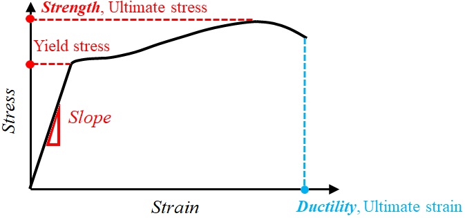
During the test, associated values for the force and displacement are recorded and converted into stress and strain (Fig. 1-12). The stress-strain curve shows the material characteristics such as elasticity, ductility, strength and toughness.
For most material, the curve consists of two regions (Fig. 1-12):
The linear or elastic part in which the stress-strain relationship is linear, and after removing the load, the specimen goes back to its initial shape.
And the nonlinear or plastic part in which the stress and strain are not proportional, and after unloading, permanent deformation is observed in the specimen.

The slope of the elastic part is called Young’s modulus, and determines the stiffness of the material (Fig. 1-13). The stress associated with the boundary of linear and nonlinear domains is called yield stress (Fig. 1-13). The ultimate stress is the maximum stress achieved in the experiment; this value measures the material strength (Fig. 1-13). The strain at the failure point is called the ultimate strain, which is a measurement of the material ductility (Fig. 1-13).
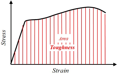
The area under the stress-strain curve defines the amount of energy, which a unit volume of the material could tolerate before failure, a material characteristic called toughness (Fig. 1-14).
Structural behaviour
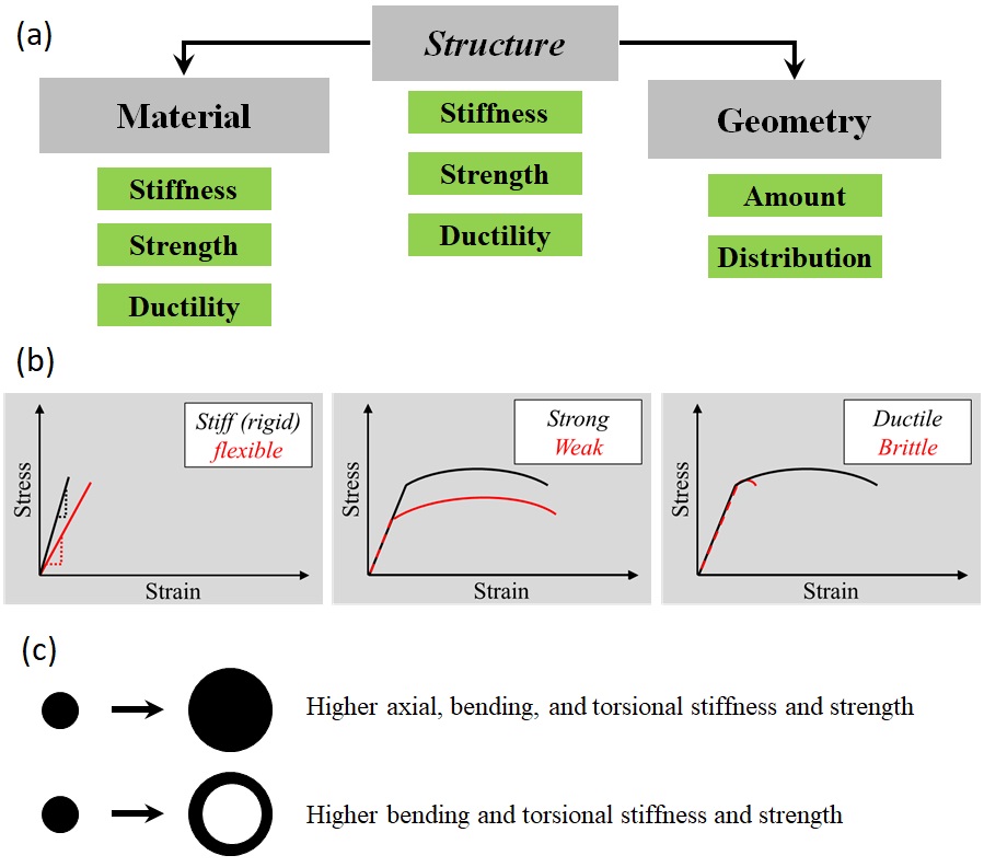
Mechanical behaviour of a structure could be confused with material behaviour. Structural behaviour is the relationship between the applied forces to the object, and the induced displacements. While, material behaviour refers to the stress-strain relationship (Fig. 1-15). Structural behaviour is dependent on material used in the structure, as well as the geometry of the structure. Material characteristics such as stiffness, strength, and ductility, all affect the structural behaviour. Additionally, geometry of the structure, including the amount and distribution of the material, could considerably change the properties of the structure (Fig. 1-15).
