Displacement and Strain: Description of Motion
The geometry of a continuum body can be represented mathematically by “embedding” it in a Euclidean Vector Space ![]() where every material point in the body can be represented by a unique vector in the space. We denote the set of vectors corresponding to the material points by
where every material point in the body can be represented by a unique vector in the space. We denote the set of vectors corresponding to the material points by ![]() . The embedding is called a “configuration”. An analyst is usually interested in comparing a “deformed” configuration
. The embedding is called a “configuration”. An analyst is usually interested in comparing a “deformed” configuration ![]() with an “undeformed” or a “reference” configuration
with an “undeformed” or a “reference” configuration ![]() . Traditionally, elements of the deformed configuration are denoted by
. Traditionally, elements of the deformed configuration are denoted by ![]() while elements in the reference configuration are denoted by
while elements in the reference configuration are denoted by ![]() . The deformed configuration can be assumed to be a function
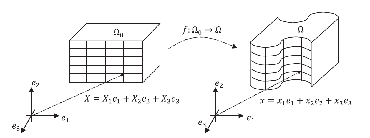
. The deformed configuration can be assumed to be a function ![]() such that
such that ![]() (Figure 1). In the majority of continuum mechanics applications, the following are the major restrictions on the possible choices of the position function
(Figure 1). In the majority of continuum mechanics applications, the following are the major restrictions on the possible choices of the position function ![]() .
.
- First, we assume that the deformation between configurations preserves the distinction between material points, i.e., that material is not flattened out or lost during configuration. This restricts
 to be bijective.
 - Second, we assume that material points don’t change their neighbours, i.e., no cracks or rearrangement of material points occur during deformation. This restricts
 to be continuous.
 - In most applications we add the third restriction of being “smooth” or “differentiable” on the possible choices for
 . This ensures that straight lines on the reference configuration deform into smooth curves in the deformed configuration. This allows the calculation of derivatives and the definition of “strain”.
The displacement function of the body (termed the displacement field) is denoted by the function ![]() such that:
such that:
![]()

A geometric object is embedded in ![]() :
: ![]() is the set of vectors representing the reference configuration, while
is the set of vectors representing the reference configuration, while ![]() is the set representing the deformed configuration.
is the set representing the deformed configuration.
In the following section a few simple examples of deformations along with their position and displacement functions are presented.
