PROJECT
Understanding the collapse of a hotel walkaway
Introduction
The Hyatt Regency Kansas City Hotel, today known as Sheraton at Crown Center, is a 40-story building opened to the public in July of 1980.The hotel featured a large lobby including a multi-story atrium spanned by north-to-sought walkways elevated to the second, third, and forth floors. The third and 4th floor walkways were suspended from the ceiling with steel rods, and the 2nd walkway was suspended from the 4th floor walkway. Figure 1 schematically demonstrates the walkways. A photo of the walkways and the lobby is available here.
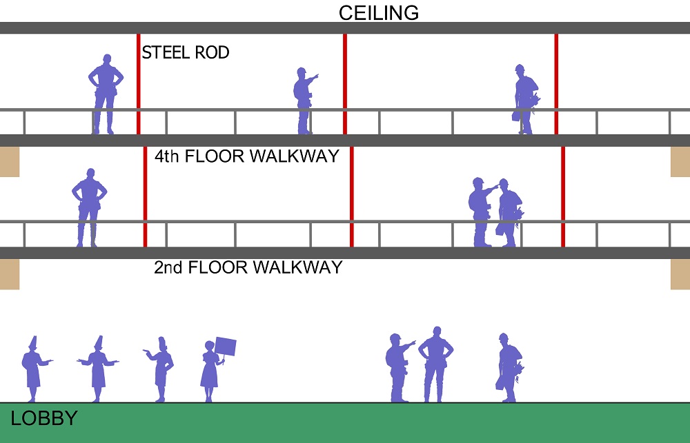
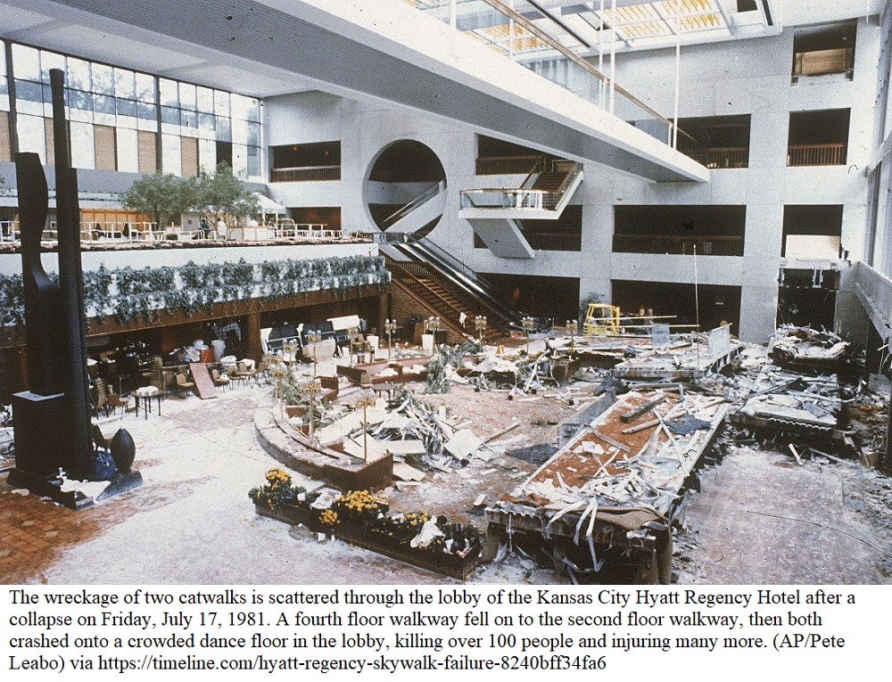
Each walkway, made of concrete, steel, and glass, was 37 meters long and weighted about 290 kN, equivalent to 29,000 kg of mass. On July 17th, 1981 when 1,600 people were on the lobby for a dance event, the 2nd and 4th floor walkways suddenly collapsed. At the time of the disaster, the 2nd and the 4th floor walkways held about 40 and 20 spectators respectively. This tragic disaster caused 114 death and 216 injured people. Figure 2 shows the collapsed walkways and the wreckage scattered in the lobby.
Structural cause of the disaster
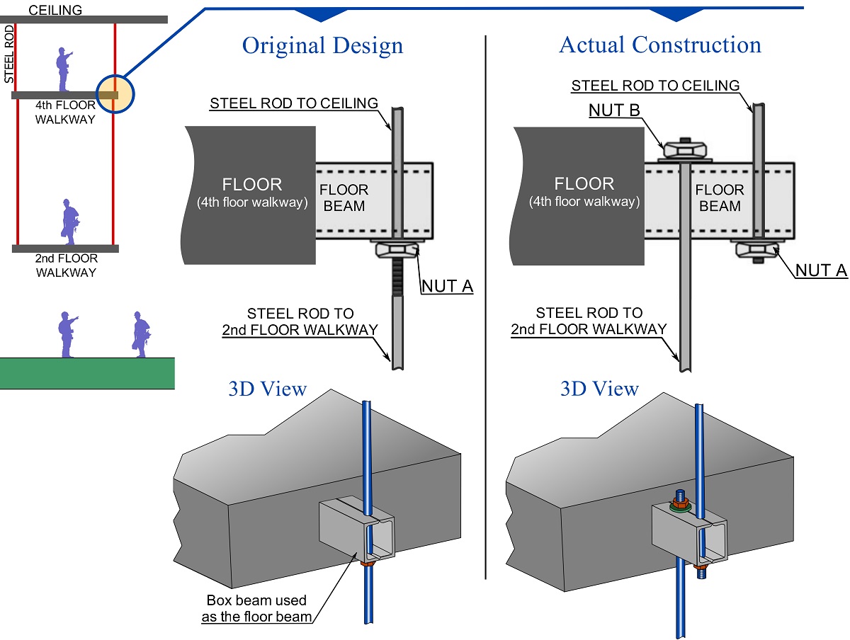
From a structural perspective, the cause of the disaster was failure at the connections of the 4th floor walkway to the steel rod. The failure occurred as the connections could not resist the extra weight of the number of people stepped on the 4th and the 2nd floor walkways. The serious question that comes to the mind is, had the connections not been designed properly to resist all the possible loads? The answer is yes, the original design of the connections was approved and supposed to withstand the loads, however, the contractor manufacturing the steel rods altered the original design of the connection right before the construction. The original design was revised because the contractor thought or felt there would be difficulties and damage to the connections during the construction. Unfortunately, the new design was not explicitly sent to a structural engineering company to be checked. Figure 3 demonstrates the original and the actual construction of a rod-walkway connection at the 4th floor walkway. In the original design, a steel rod connected to the ceiling continuously passed through the 4th floor walkway toward the 2nd floor walkway. The rod was connected to a floor beam of a walkway by a nut. In the actual construction, however, the rod was split at the 4th floor walkway as shown in the figure.
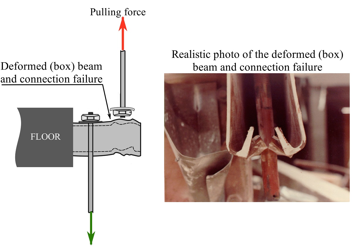
As people stepped on the walkways and load increased on the 2nd and 4th floor walkways, the steel rod (and its nut) got pulled out of the 4th floor walkway beam and the actual construction failed. Figure 4 shows the failure mechanism of the connection.
You can watch the failure mechanism in the following video.
In this project, you (as a designer) will find and compare the forces of the original design and the actual construction of the connection to determine the optimum connection to support the walkways. Then, you should be able to comprehend how the change in the design led to the connection failure and the disaster.
Part 1
Consider two options for the connection: Option 1 (the original design) entails the steel rods continuously passing through the 4th floor walkway toward the 2nd floor while Option 2 (actual construction) involves staggering the rods such that sperate rods are used between walkways. The two possible connection types along with the walkway loads are presented in Fig. 5 below. Each walkway carries a resultant load of 290 kN at the midspan.
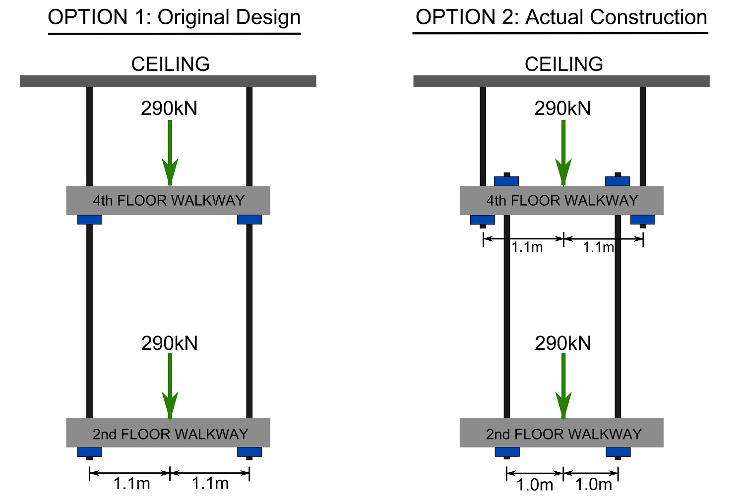
1- Draw the FBD of each walkway for each option. Hint: imaginarily isolate each walkway floor along with a portion of its bars. Bars behave like cables (they only resist pulling forces).
2- Calculate the forces in the bars and compare the bar forcs of each option with eachother.
Part 2
As you can see from the results of the previous part, the forces of the bars of each walkway are identical regardless of the options. So, what makes the two options different from each other, and what caused the connection of the 4th floor walkway in option 2 to fail. To answer this question, consider the FBD of the connection attaching the 4th floor walkway to the bar extended to the ceiling for each option as shown in Fig. 6 below and answer the follwoing questions.
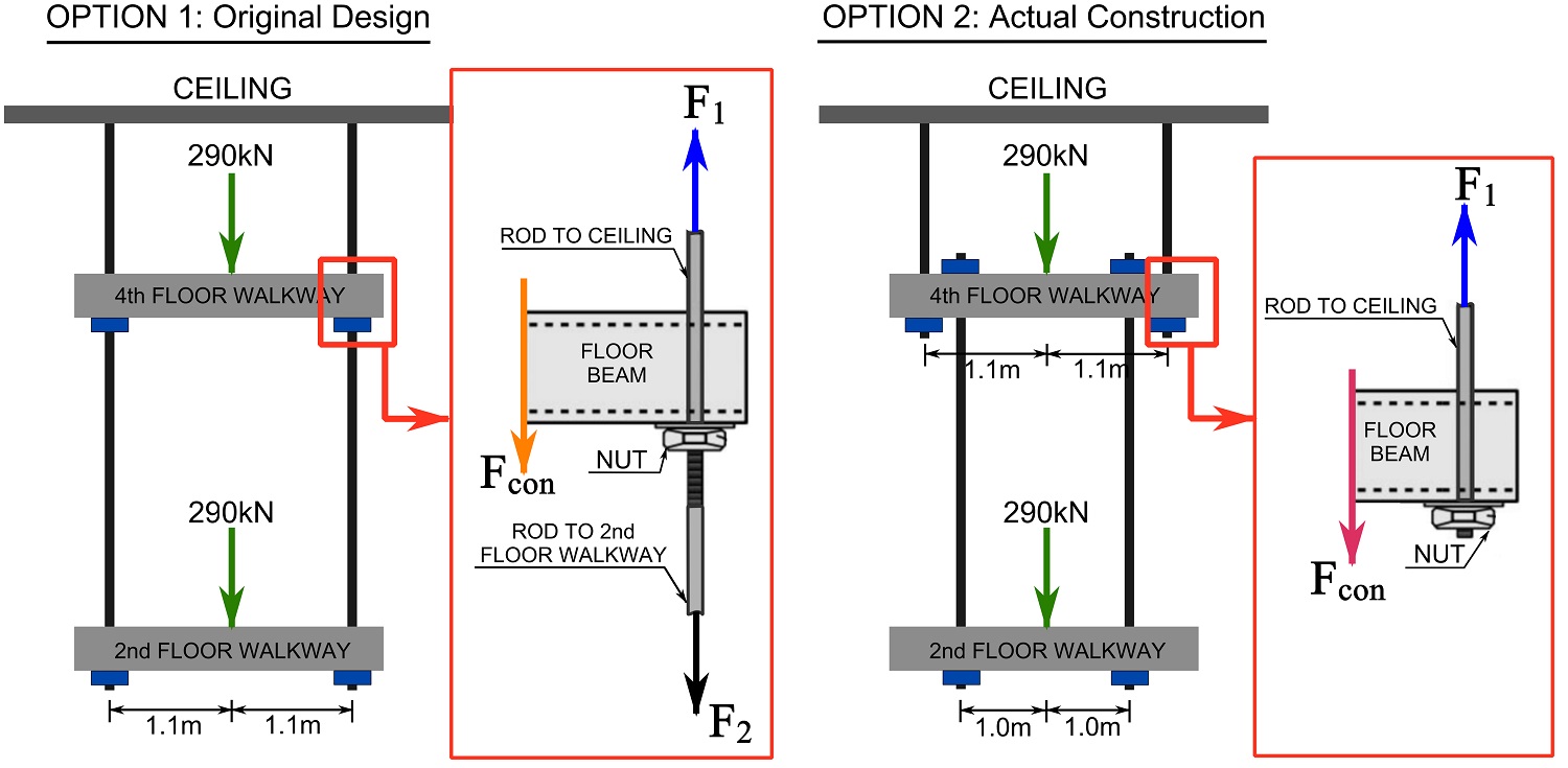
1- Using the rod forces, which you obtained in part 1, calculate the connection force Fcon of the 4th floor walkway regarding each option.
2- Compare the connection forces of both options with eachother. How many times is the connection force of the actual construction (i.e real situation) larger that that of the original design? Which option is optimum?
3- Can you now explain the reason of the failure?